ELECTRONICALLY CONTROLLED BRAKE SYSTEM, Diagnostic DTC:C1365/54

| DTC Code | DTC Name |
|---|---|
| C1365/54 | Accumulator Pressure Sensor Malfunction |
DESCRIPTION
The accumulator pressure sensor is built into the brake actuator.
The skid control ECU detects the accumulator pressure from the data sent from the accumulator pressure sensor, and then runs and stops the pump motor by operating the motor relay.
DTCs may be output if the accumulator pressure drops due to frequent braking (this is not a malfunction).
| DTC Code | INF Code | DTC Detection Condition | Trouble Area |
|---|---|---|---|
| C1365/54 | 211 | Sensor power 1 (VCM) voltage is 4.7 V or less or 5.3 V or more for at least 0.05 seconds. |
|
| ↑ | 212 | Accumulator pressure sensor output voltage (PAC1) is less than 0.25 V or 4.53 V or more for at least 0.05 seconds. | ↑ |
| ↑ | 214 | While the motor is off, the total of the wheel cylinder pressure sensor values of all 4 wheels increases but the accumulator pressure changes little for 0.5 seconds or more. | ↑ |
| ↑ | 215 | Accumulator pressure sensor output voltage (PAC1) is stuck at 4.53 V or less. | ↑ |
WIRING DIAGRAM
Refer to DTCs C1246/46, C1281/81 and C1364/61 Click here.
INSPECTION PROCEDURE
Note
When replacing the skid control ECU or brake actuator assembly, perform initialization and calibration of the linear solenoid valve Click here.
PROCEDURE
-
CHECK HARNESS AND CONNECTOR (SKID CONTROL ECU - BRAKE ACTUATOR)
-
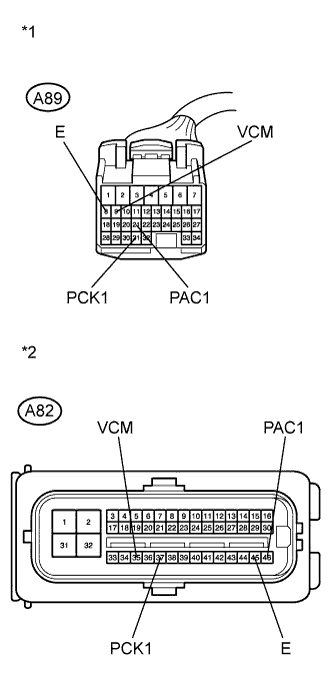
Text in Illustration *1 Front view of wire harness connector
(to Skid Control ECU)
*2 Front view of wire harness connector
(to Brake Actuator)
Make sure that there is no looseness at the locking part and the connecting part of the connectors.
-
Disconnect the skid control ECU connector and the brake actuator connector.
-
Measure the resistance according to the value(s) in the table below.
Standard Resistance Tester Connection Condition Specified Condition A89-8 (E) - A82-45 (E) Always Below 1 Ω A89-8 (E) - Body ground Always 10 kΩ or higher A89-9 (VCM) - A82-35 (VCM) Always Below 1 Ω A89-9 (VCM) - Body ground Always 10 kΩ or higher A89-21 (PAC1) - A82-46 (PAC1) Always Below 1 Ω A89-21 (PAC1) - Body ground Always 10 kΩ or higher A89-31 (PCK1) - A82-37 (PCK1) Always Below 1 Ω A89-31 (PCK1) - Body ground Always 10 kΩ or higher
NG 
REPAIR OR REPLACE HARNESS OR CONNECTOR
OK 
-
-
INSPECT SKID CONTROL ECU (SENSOR OUTPUT)
-
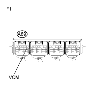
Text in Illustration *1 Component without harness connected
(Skid Control ECU)
Reconnect the skid control ECU connector and the brake actuator connector.
-
Turn the power switch on (IG).
-
Measure the voltage according to the value(s) in the table below.
Standard Voltage Tester Connection Switch Condition Specified Condition A89-9 (VCM) - Body ground Power switch on (IG) 4.75 to 5.25 V
NG
REPLACE SKID CONTROL ECU Click here
OK
-
-
INSPECT SKID CONTROL ECU (SENSOR INPUT)
-
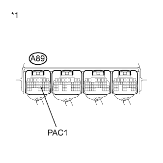
Text in Illustration *1 Component without harness connected
(Skid Control ECU)
Depress the brake pedal to operate the pump motor, and then check that the pump motor stops.
-
Measure the voltage according to the value(s) in the table below.
Note
Do not depress the brake pedal until the pump motor stops and the voltage check is finished in order to keep the accumulator pressure.
Standard Voltage Tester Connection Switch Condition Specified Condition A89-21 (PAC1) - Body ground Power switch on (IG) 3 to 4.7 V
NG
REPLACE BRAKE ACTUATOR ASSEMBLY Click here
OK
-
-
READ VALUE USING INTELLIGENT TESTER (ACCUMULATOR PRESSURE SENSOR)
-
Turn the power switch off.
-
Connect the intelligent tester to the DLC3.
-
Turn the power switch on (IG).
-
Select the Data List on the intelligent tester Click here.
ABS/VSC/TRC Tester Display Measurement Item/Range Normal Condition Diagnostic Note Accumulator Sensor Accumulator pressure sensor /
Min.: 0 V, Max.: 5 V
Specified value: 2.6 to 3.8 V When brake fluid is stored in the accumulator: Accumulator pressure changes in accordance with volume of fluid stored in the accumulator -
Depress the brake pedal 4 or 5 times to operate the pump motor, and check the output value on the intelligent tester with the motor stopped (brake pedal not depressed).
OK Accumulator pressure sensor voltage does not drop.
NG
REPLACE BRAKE ACTUATOR ASSEMBLY Click here
OK
-
-
RECONFIRM DTC
-
Turn the power switch off.
-
Clear the DTCs Click here.
-
Perform a road test.
-
Check if the same DTC is recorded Click here.
Result Result Proceed to DTC (C1365/54) is not output A DTC (C1365/54) is output B
B
REPLACE SKID CONTROL ECU Click here
A 
CHECK FOR INTERMITTENT PROBLEMS Click here
-