ELECTRONICALLY CONTROLLED BRAKE SYSTEM, Diagnostic DTC:C1252/52, C1253/53

| DTC Code | DTC Name |
|---|---|
| C1252/52 | Brake Booster Pump Motor on Time Abnormally Long |
| C1253/53 | Pump Motor Relay Malfunction |
DESCRIPTION
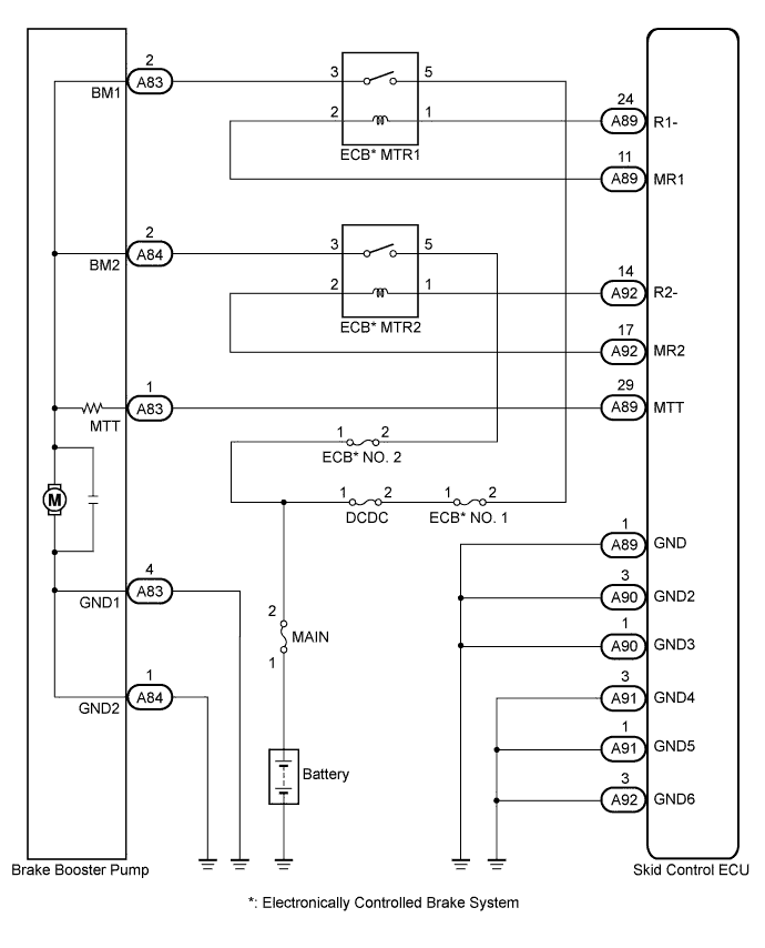
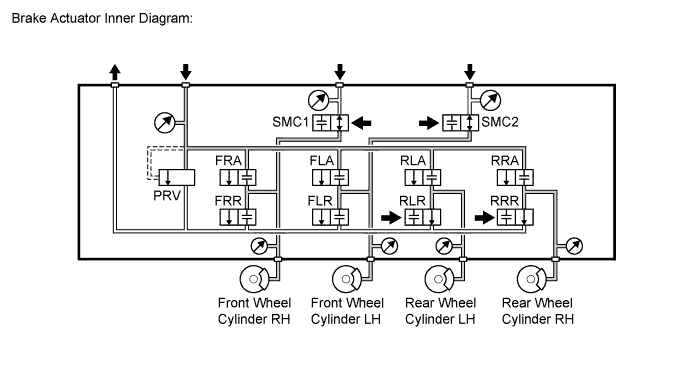
The skid control ECU detects decreases in the accumulator pressure according to the data from the accumulator pressure sensor, and then starts and stops the pump motor by operating the motor relay.
The skid control ECU usually drives the motor relay 1 for electronically controlled brake system control, and the motor relay 2 for ABS control. If either of them is malfunctioning, the other will substitute.
| DTC Code | INF Code | DTC Detection Condition | Trouble Area |
|---|---|---|---|
| C1252/52 | 130 | Motor relay is on for at least 3 minutes. |
|
| C1253/53 | 134 | MTT input is less than 3.5 V for at least 1 second or more when linear solenoid power source voltage 1 (BS1) is 9.5 V or more, either of +BI1 or +BI2 voltage is 7 V or more, and motor relay 1 is on. |
|
| ↑ | 138 | MTT input is less than 3.5 V for at least 1 second or more when linear solenoid power source voltage 2 (BS2) is 9.5 V or more, either of +BI1 or +BI2 voltage is 7 V or more, and motor relay 1 is on. |
|
| ↑ | 140 | MTT input is 3.5 V or more for at least 2 seconds when motor relay 1 and 2 are off. |
|
*: Electronically Controlled Brake System
WIRING DIAGRAM
INSPECTION PROCEDURE
Note
When replacing the skid control ECU or brake actuator assembly, perform initialization and calibration of the linear solenoid valve Click here.
PROCEDURE
-
PERFORM ACTIVE TEST USING INTELLIGENT TESTER (ABS MOTOR RELAY)
-
Connect the intelligent tester to the DLC3.
-
Turn the power switch on (IG).
-
Select the Active Test on the intelligent tester Click here.
ABS/VSC/TRC Tester Display Test Part Control Range Diagnostic Note ECB* Motor Relay ABS motor relay Relay ON/OFF Operation sound of relay (clicking sound) and motor can be heard ECB* Motor Relay2 ABS motor relay 2 Relay ON/OFF Operation sound of relay (clicking sound) and motor can be heard *: Electronically Controlled Brake System
-
Check the operation sound of the ABS motor relay and motor when operating it using the intelligent tester.
OK The operation sound of the ABS motor relay and motor should be heard.
NG 
INSPECT ECB* NO. 1, 2 FUSE Click here
OK 
-
-
INSPECT BRAKE BOOSTER PUMP
-
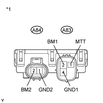
Text in Illustration *1 Component without harness connected
(Brake Booster Pump)
Turn the power switch off.
-
Make sure that there is no looseness at the locking part and the connecting part of the connectors.
-
Disconnect the brake booster pump connectors.
-
Measure the resistance according to the value(s) in the table below.
Standard Resistance Tester Connection Condition Specified Condition A83-2 (BM1) - A83-4 (GND1) Always Below 10 Ω A84-2 (BM2) - A83-4 (GND1) Always Below 10 Ω A83-2 (BM1) - A84-2 (BM2) Always Below 1 Ω A83-4 (GND1) - A84-1 (GND2) Always Below 1 Ω A83-2 (BM1) - A83-1 (MTT) Always 950 to 1050 Ω A84-2 (BM2) - A83-1 (MTT) Always 950 to 1050 Ω
NG 
REPLACE BRAKE BOOSTER PUMP Click here
OK
-
-
CHECK HARNESS AND CONNECTOR (SKID CONTROL ECU - BRAKE BOOSTER PUMP)
-
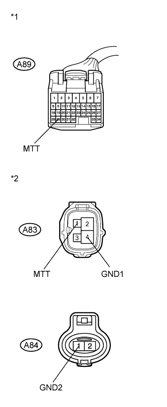
Text in Illustration *1 Front view of wire harness connector
(to Skid Control ECU)
*2 Front view of wire harness connector
(to Brake Booster Pump)
Make sure that there is no looseness at the locking part and the connecting part of the connector.
-
Disconnect the skid control ECU connector.
-
Measure the resistance according to the value(s) in the table below.
Standard Resistance Tester Connection Condition Specified Condition A89-29 (MTT) - A83-1 (MTT) Always Below 1 Ω A89-29 (MTT) - Body ground Always 10 kΩ or higher A83-4 (GND1) - Body ground Always Below 1 Ω A84-1 (GND2) - Body ground Always Below 1 Ω
NG
REPAIR OR REPLACE HARNESS OR CONNECTOR
OK
-
-
READ VALUE USING INTELLIGENT TESTER (ACCUMULATOR PRESSURE SENSOR)
-
Reconnect the skid control ECU connector and the brake booster pump connectors.
-
Connect the intelligent tester to the DLC3.
-
Turn the power switch on (IG).
-
Select the Data List on the intelligent tester Click here.
ABS/VSC/TRC Tester Display Measurement Item/Range Normal Condition Diagnostic Note Accumulator Sensor Accumulator pressure sensor /
Min.: 0 V, Max.: 5 V
Specified value: 2.6 to 3.8 V When brake fluid is stored in the accumulator: Accumulator pressure changes in accordance with volume of fluid stored in the accumulator -
Depress the brake pedal 4 or 5 times to operate the pump motor, and check the output value on the intelligent tester with the motor stopped (not braking).
OK Accumulator pressure sensor output voltage does not drop.
NG
PERFORM ACTIVE TEST USING INTELLIGENT TESTER (SOLENOID VALVE) Click here
OK
-
-
RECONFIRM DTC
-
Turn the power switch off.
-
Clear the DTCs Click here.
-
Turn the power switch on (IG).
-
Check if the same DTC is recorded Click here.
Result Result Proceed to DTCs (C1252/52 and C1253/53) are not output A DTCs (C1252/52 and/or C1253/53) are output B
B
REPLACE SKID CONTROL ECU Click here
A 
CHECK FOR INTERMITTENT PROBLEMS Click here
-
-
INSPECT ECB* NO. 1, 2 FUSE
-
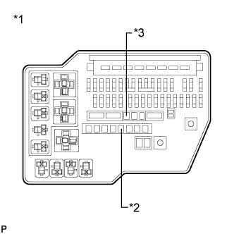
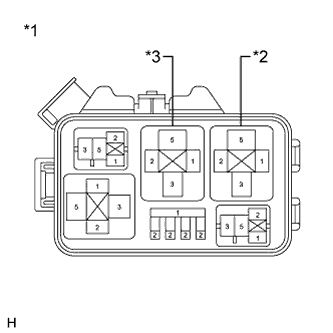
Text in Illustration *1 Engine Room Relay Block *2 ECB* NO. 1 Fuse *3 ECB* NO. 2 Fuse Turn the power switch off.
-
Remove the fusible link block from the engine room relay block.
-
Check if the fusible link is melted.
OK The fusible link is not melted. -
Measure the resistance according to the value(s) in the table below.
Standard Resistance Tester Connection Condition Specified Condition ECB* NO. 1 (50 A) fuse - Body ground Always Below 1 Ω ECB* NO. 2 (50 A) fuse - Body ground Always Below 1 Ω *: Electronically Controlled Brake System
NG
REPLACE FUSIBLE LINK BLOCK (ECB* NO. 1, 2 FUSE)
OK
-
-
INSPECT ABS MOTOR RELAY (ECB* MTR1, 2)
-
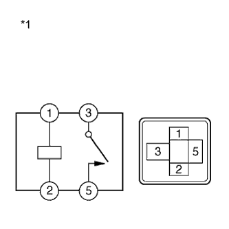
Text in Illustration *1 ABS Motor Relay (ECB* MTR1, 2 Relay) Install the fusible link block to the engine room relay block .
-
Remove the ECB* MTR1 relay and the ECB* MTR2 relay.
-
Measure the resistance according to the value(s) in the table below.
Standard Resistance Tester Connection Condition Specified Condition 3 - 5 Voltage is not applied between terminals 1 and 2 10 kΩ or higher 3 - 5 Voltage is applied between terminals 1 and 2 Below 1 Ω *: Electronically Controlled Brake System
NG
REPLACE ABS MOTOR RELAY (ECB* MTR1, 2)
OK
-
-
INSPECT ENGINE ROOM NO. 2 RELAY BLOCK (POWER SOURCE TERMINAL)
-
Text in Illustration *1 Engine Room No. 2 Relay Block *2 ECB* MTR1 Relay *3 ECB* MTR2 Relay Measure the voltage according to the value(s) in the table below.
Standard Voltage Tester Connection Condition Specified Condition ECB* MTR1 relay terminal 5 - Body ground Always 11 to 14 V ECB* MTR2 relay terminal 5 - Body ground Always 11 to 14 V *: Electronically Controlled Brake System
NG
REPAIR OR REPLACE HARNESS OR CONNECTOR (POWER SOURCE CIRCUIT)
OK
-
-
CHECK HARNESS AND CONNECTOR (BRAKE BOOSTER PUMP - ENGINE ROOM NO. 2 RELAY BLOCK)
-
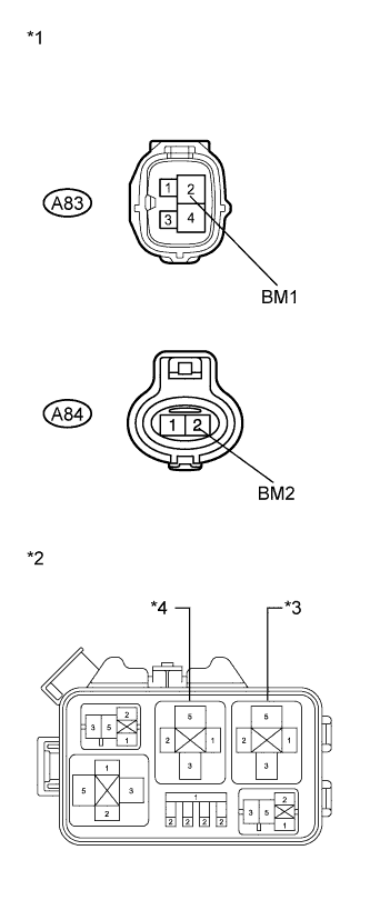
Text in Illustration *1 Front view of wire harness connector
(to Brake Booster Pump)
*2 Engine Room No. 2 Relay Block *3 ECB* MTR1 Relay *4 ECB* MTR2 Relay Make sure that there is no looseness at the locking part and the connecting part of the connectors.
-
Disconnect the brake booster pump connectors.
-
Measure the resistance according to the value(s) in the table below.
Standard Resistance Tester Connection Condition Specified Condition A83-2 (BM1) - ECB* MTR1 relay terminal 3 Always Below 1 Ω A83-2 (BM1) - Body ground Always 10 kΩ or higher A84-2 (BM2) - ECB* MTR2 relay terminal 3 Always Below 1 Ω A84-2 (BM2) - Body ground Always 10 kΩ or higher *: Electronically Controlled Brake System
NG
REPAIR OR REPLACE HARNESS OR CONNECTOR
OK
-
-
CHECK HARNESS AND CONNECTOR (SKID CONTROL ECU - ENGINE ROOM NO. 2 RELAY BLOCK)
-
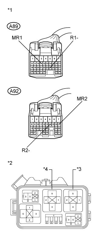
Text in Illustration *1 Front view of wire harness connector
(to Skid Control ECU)
*2 Engine Room No. 2 Relay Block *3 ECB* MTR1 Relay *4 ECB* MTR2 Relay Make sure that there is no looseness at the locking part and the connecting part of the connectors.
-
Disconnect the skid control ECU connectors.
-
Measure the resistance according to the value(s) in the table below.
Standard Resistance Tester Connection Condition Specified Condition A89-11 (MR1) - ECB* MTR1 relay terminal 2 Always Below 1 Ω A89-11 (MR1) - Body ground Always 10 kΩ or higher A89-24 (R1-) - ECB* MTR1 relay terminal 1 Always Below 1 Ω A89-24 (R1-) - Body ground Always 10 kΩ or higher A92-14 (R2-) - ECB* MTR2 relay terminal 1 Always Below 1 Ω A92-14 (R2-) - Body ground Always 10 kΩ or higher A92-17 (MR2) - ECB* MTR2 relay terminal 2 Always Below 1 Ω A92-17 (MR2) - Body ground Always 10 kΩ or higher *: Electronically Controlled Brake System
NG
REPAIR OR REPLACE HARNESS OR CONNECTOR
OK
REPLACE SKID CONTROL ECU Click here
-
-
PERFORM ACTIVE TEST USING INTELLIGENT TESTER (SOLENOID VALVE)
-
Select the Active Test on the intelligent tester Click here.
Tech Tips
The Active Test can be performed when the following conditions are met.
-
ABS main relays 1 and 2 are on.
-
Shift lever is in P.
-
Parking brake is applied.
-
Vehicle speed is 0 km/h (0 mph).
ABS/VSC/TRC Tester Display Test Part Control Range Diagnostic Note ECB* Solenoid (SMC1) Master cut solenoid (SMC1) Solenoid ON/OFF Operation sound of solenoid (clicking sound) can be heard ECB* Solenoid (SMC2) Master cut solenoid (SMC2) Solenoid ON/OFF Operation sound of solenoid (clicking sound) can be heard ECB* Solenoid (SLRRL) Value Close Linear solenoid (RLR) valve Valve close ON/OFF Operation sound of solenoid (clicking sound) can be heard ECB* Solenoid (SLRRR) Value Close Linear solenoid (RRR) valve Valve close ON/OFF Operation sound of solenoid (clicking sound) can be heard *: Electronically Controlled Brake System
-
-
Perform the Active Test of the solenoid using the intelligent tester.
-
Select the Data List on the intelligent tester Click here.
ABS/VSC/TRC Tester Display Measurement Item/Range Normal Condition Diagnostic Note FR W/C Sensor FR wheel cylinder pressure sensor / Min.: 0 V, Max.: 5 V When brake pedal is released: 0.3 to 0.7 V Reading increases when brake pedal is depressed FL W/C Sensor FL wheel cylinder pressure sensor / Min.: 0 V, Max.: 5 V When brake pedal is released: 0.3 to 0.7 V Reading increases when brake pedal is depressed RR W/C Sensor RR wheel cylinder pressure sensor / Min.: 0 V, Max.: 5 V When brake pedal is released: 0.3 to 0.7 V Reading increases when brake pedal is depressed RL W/C Sensor RL wheel cylinder pressure sensor / Min.: 0 V, Max.: 5 V When brake pedal is released: 0.3 to 0.7 V Reading increases when brake pedal is depressed -
Check that the output value of each wheel cylinder does not increase.
OK The output value of each wheel cylinder does not increase. Tech Tips
If any output value increases, there may be a brake fluid leak in the brake actuator.
NG
REPLACE BRAKE ACTUATOR ASSEMBLY Click here
OK
REPLACE BRAKE BOOSTER PUMP Click here
-