REAR WHEEL ALIGNMENT ADJUSTMENT

Note
If the wheel alignment has been adjusted, and if suspension or underbody components have been removed/installed or replaced, be sure to perform the following initialization procedure in order for the system to function normally:
-
Perform zero point calibration of the yaw rate and acceleration sensor.
-
PRECAUTION (w/ Air Suspension)
-
INSPECT TIRES
-
MEASURE VEHICLE HEIGHT
Note
-
Before inspecting the wheel alignment, adjust the vehicle height to the specified value.
-
Be sure to perform measurement on a level surface.
-
If it is necessary to go under the vehicle for measurement, confirm that the parking brake is applied and the vehicle is secured with chocks.
-
Bounce the vehicle up and down at the corners to stabilize the suspension.
-
Measure the vehicle height.
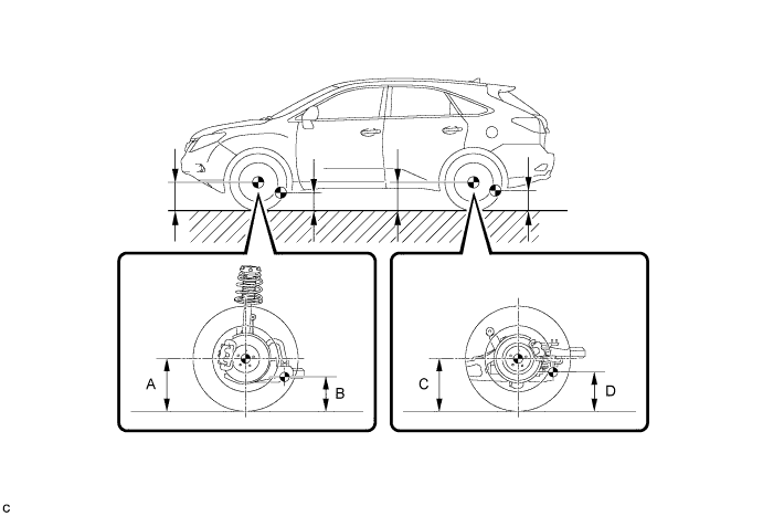
Measurement points A Ground clearance of front wheel center B Ground clearance of front lower suspension arm bushing set bolt center C Ground clearance of rear wheel center D Ground clearance of rear No. 2 suspension arm adjust bolt center Vehicle Height (Unloaded Vehicle) Model Front A - B Rear C - D 2WD 123.2 mm (4.85 in.) 50.8 mm (2.00 in.) AWD (w/o Air Suspension) 124.6 mm (4.91 in.) 53.0 mm (2.09 in.) AWD (w/ Air Suspension) 120 mm (4.72 in.) 58 mm (2.28 in.)
-
-
INSPECT CAMBER
Camber (Unloaded Vehicle) Model Camber Inclination Right-left Difference 2WD -0°35' +/- 45' (-0.58° +/- 0.75°) 45' (0.75°) or less AWD (w/o Air Suspension) -0°35' +/- 45' (-0.58° +/- 0.75°) AWD (w/ Air Suspension) -0°49' +/- 45' (-0.82° +/- 0.75°) Tech Tips
Camber is not adjustable. If the measurement is not within the specified range, inspect the suspension parts for damage and/or wear, and replace them if necessary.
-
INSPECT TOE-IN
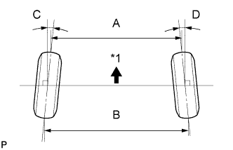
Text in Illustration *1 Front of the Vehicle Toe-in (Unloaded Vehicle) Model Specified Condition w/o Air Suspension C + D: 0°05' +/- 0°10' (0.08° +/- 0.17°) B - A: 1.0 +/- 2.0 mm (0.0394 +/- 0.0787 in.) w/ Air Suspension C + D: 0°13' +/- 0°10' (0.21° +/- 0.17°) B - A: 2.5 +/- 2.0 mm (0.0984 +/- 0.0787 in.) If the toe-in is not within the specified range, adjust it at the rear No. 2 suspension arms.
Tech Tips
Measure "B - A" only when "C + D" cannot be measured.
-
ADJUST TOE-IN
-
Measure the distance between each wheel disc and the center of the toe-adjusting cam.
Difference in the distance between each wheel disc and the center of the toe-adjusting cam 1.0 mm (0.0394 in.) or less If the left-right difference is not within the specified range, adjust it by following the procedure below.
-
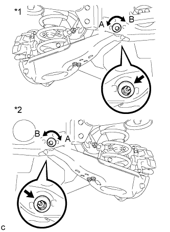
Text in Illustration *1 LH Side *2 RH Side Loosen the toe-adjust cam set nuts.
-
If the distance between each wheel disc and the center of the toe-adjusting cam is not within the specified range, adjust it by following the procedure below.
-
If the toe-in measurement is greater than the specified range, extend the shorter rear No. 2 suspension arm assembly by rotating the adjust cams in the direction of arrow B in the illustration.
-
If the toe-in measurement is less than the specified range, shorten the longer rear No. 2 suspension arm assembly by rotating the adjust cams in the direction of arrow A in the illustration.
-
Measure the toe-in.
-
-
Turn the adjust cams by an equal amount to adjust the toe-in.
Tech Tips
-
Try to adjust the toe-in to the center of the specified range.
-
One graduation of each adjusting cam will adjust the toe-in by approximately 2.1 mm (0.0827 in.).
-
-
Tighten the toe-adjust cam set nuts.
- Torque:
- 100 N*m { 1020 kgf*cm, 74 ft.*lbf }
Note
The final torque must be applied under standard vehicle height conditions.
-
-
PLACE FRONT WHEELS FACING STRAIGHT AHEAD
-
PERFORM YAW RATE AND ACCELERATION SENSOR ZERO POINT CALIBRATION
Tech Tips
Perform the yaw rate and acceleration sensor zero point calibration Click here.
-
PERFORM INITIALIZATION
Tech Tips
Some systems need to be initialized after the wheel alignment is adjusted Click here.