DC / DC CONVERTER INSTALLATION

-
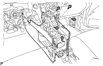
INSTALL POWER STEERING CONVERTER ASSEMBLY (w/o Active Stabilizer System)
CAUTION:
Wear insulated gloves during this procedure.
-
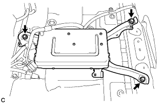
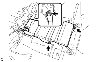
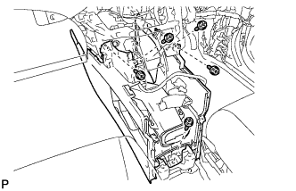
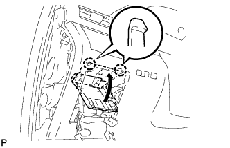
Install the power steering converter assembly with the 3 bolts.
- Torque:
- 12 N*m { 117 kgf*cm, 8 ft.*lbf }
CAUTION:
-
Wear insulated gloves during this procedure.
-
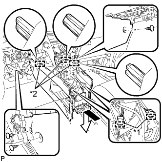
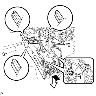
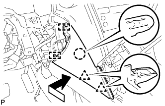
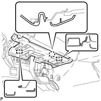
Wrap insulating tape around the terminals of the removed high-voltage cables and connectors to insulate them.
-
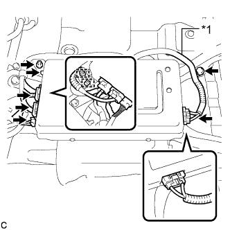
Text in Illustration *1 High-voltage Cable Connect each connector and install the 2 clamps to the power steering converter assembly.
-
Install the high-voltage cables to the power steering converter assembly with the bolt.
- Torque:
- 8.0 N*m { 82 kgf*cm, 71 in.*lbf }
-
Check that the high-voltage cables are securely connected to the power steering converter assembly.
Note
Ensure that the connectors are securely connected.
-
-
INSTALL POWER STEERING CONVERTER ASSEMBLY (w/ Active Stabilizer System)
CAUTION:
Wear insulated gloves during this procedure.
-
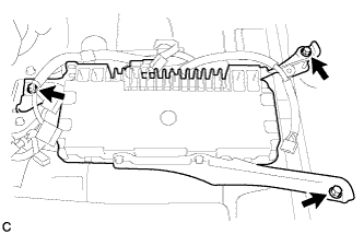
Install the power steering converter assembly with the 3 bolts.
- Torque:
- 12 N*m { 117 kgf*cm, 8 ft.*lbf }
CAUTION:
-
Wear insulated gloves during this procedure.
-
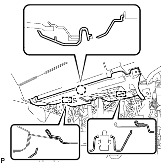
Wrap insulating tape around the terminals of the removed high-voltage cables and connectors to insulate them.
-
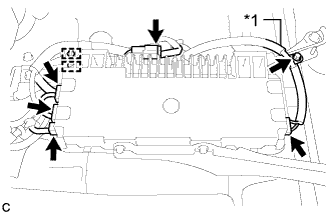
Text in Illustration *1 High-voltage Cable Connect each connector and install the 2 clamps to the power steering converter assembly.
-
Install the high-voltage cables to the power steering converter assembly with the bolt.
- Torque:
- 8.0 N*m { 82 kgf*cm, 71 in.*lbf }
-
Check that the high-voltage cables are securely connected to the power steering converter assembly.
Note
Ensure that the connectors are securely connected.
-
-
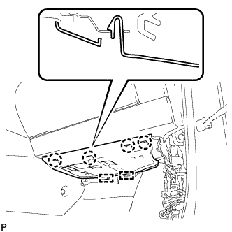
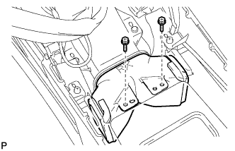
INSTALL NO. 1 POWER STEERING BRACKET
-
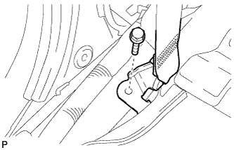
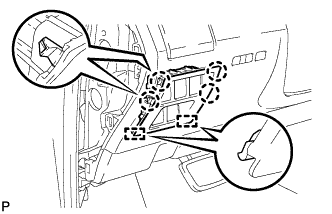
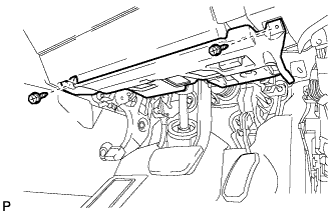
Install the No. 1 power steering bracket with the 3 nuts.
- Torque:
- 8.5 N*m { 87 kgf*cm, 75 in.*lbf }
-
Install the wire harness clamp to the No. 1 power steering bracket.
-
Return the floor carpet to its original position.
-
-
CONNECT FRONT SEAT OUTER BELT ASSEMBLY LH
-
Install the floor end of the front seat outer belt assembly with the bolt.
- Torque:
- 42 N*m { 428 kgf*cm, 31 ft.*lbf }
-
Check if the ELR locks.
Note
The check should be performed with the outer belt assembly installed.
-
With the belt assembly installed, check that the belt locks when it is pulled out quickly.
-
-
-
INSTALL LOWER CENTER PILLAR GARNISH LH
-
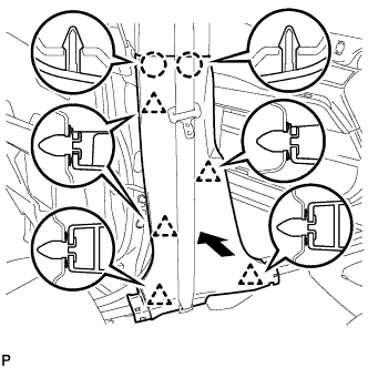
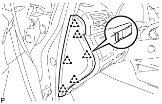
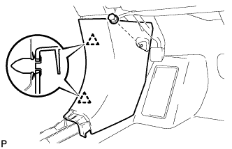
Engage the 2 claws and the 5 clips to install the lower center pillar garnish LH.
-
-
INSTALL REAR DOOR SCUFF PLATE LH
-
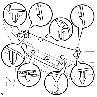
Engage the 3 clips, guide and 6 claws, and install the rear door scuff plate LH.
-
-
CONNECT FRONT SEAT OUTER BELT ASSEMBLY RH
Tech Tips
Use the same procedure for the RH side and the LH side.
-
INSTALL LOWER CENTER PILLAR GARNISH RH
Tech Tips
Use the same procedure for the RH side and the LH side.
-
INSTALL REAR DOOR SCUFF PLATE RH
Tech Tips
Use the same procedure for the RH side and the LH side.
-
INSTALL INSTRUMENT PANEL GARNISH RH (w/o Airbag Cut Off Switch)
Tech Tips
Use the same procedure as for the LH side.
-
INSTALL INSTRUMENT PANEL GARNISH RH (w/ Airbag Cut Off Switch)
-
Connect the connector.
-
Engage the 6 clips to install the instrument panel garnish RH.
-
-
INSTALL NO. 2 INSTRUMENT PANEL UNDER COVER SUB-ASSEMBLY
-
Connect the connector.
-
Engage the 2 guides and 4 claw to install the No. 2 instrument panel under cover sub-assembly.
-
-
INSTALL COWL SIDE TRIM SUB-ASSEMBLY RH
Tech Tips
Use the same procedure as for the LH side Click here.
-
INSTALL FRONT DOOR SCUFF PLATE RH
Tech Tips
Use the same procedure as for the LH side Click here.
-
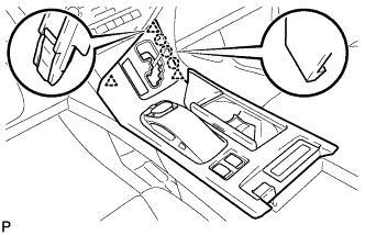
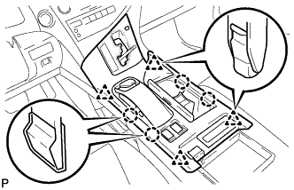
INSTALL CONSOLE BOX (for LHD)
-
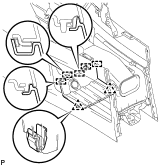
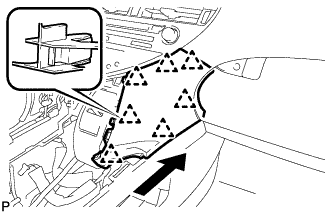
Text in Illustration *1 Clamp *2 Guide Engage the 3 guides as shown in the illustration.
-
Engage the 2 clamps.
-
Install the 3 clips.
-
Install the console box with the 5 screws <D>.
-
-
INSTALL CONSOLE BOX (for RHD)
-
Text in Illustration *1 Clamp *2 Guide Engage the 3 guides as shown in the illustration.
-
Engage the 2 clamps.
-
Install the 2 clips.
-
Install the console box with the 5 screws <D>.
-
-
INSTALL FRONT CONSOLE BOX COVER
-
Connect the connector.
-
Engage the 5 guides and 2 clips, and install the front console box cover.
-
-
INSTALL LOWER INSTRUMENT PANEL FINISH PANEL
-
Engage the 7 clips to install the lower instrument panel finish panel as shown in the illustration.
-
-
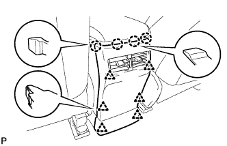
INSTALL INSTRUMENT PANEL FINISH PANEL
-
Engage the 2 guides, claw and 2 clips to install the instrument panel finish panel as shown in the illustration.
-
-
INSTALL LOWER INSTRUMENT PANEL FINISH PANEL SUB-ASSEMBLY
-
Connect each connector.
-

Engage the 8 clips and 2 guides.
-
Install the lower instrument panel finish panel sub-assembly with the 2 screws <D>.
-
Engage the 2 claws to close the cover as shown in the illustration.
-
-
INSTALL NO. 1 SWITCH HOLE BASE
-
Connect each connector.
-
Engage the 4 claws and 2 guides to install the No. 1 switch hole base.
-
-
INSTALL INSTRUMENT PANEL GARNISH LH
-
Engage the 6 clips to install the instrument panel garnish LH.
-
-
INSTALL NO. 1 INSTRUMENT PANEL UNDER COVER SUB-ASSEMBLY (for LHD)
-
Engage each clamp.
-
Connect each connector.
-
Engage the claw and 2 guides.
-

Install the No. 1 instrument panel under cover sub- assembly with the 2 screws <D>.
-
-
INSTALL NO. 1 INSTRUMENT PANEL UNDER COVER SUB-ASSEMBLY (for RHD)
-
Engage each clamp.
-
Connect each connector.
-
Engage the claw and 2 guides.
-
Install the No. 1 instrument panel under cover sub- assembly with the 2 screws <D>.
-
-
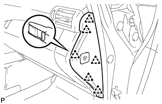
INSTALL COWL SIDE TRIM SUB-ASSEMBLY LH
-
Engage the 2 clips to install the cowl side trim sub-assembly LH.
-
Install the clip.
-
-
INSTALL FRONT DOOR SCUFF PLATE LH
-
w/ Illumination:
-
Connect the connector.
-
-
Engage the 4 clips, guide and 7 claws, and install the front door scuff plate LH.
-
-
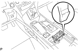
INSTALL REAR CONSOLE BOX ASSEMBLY
-
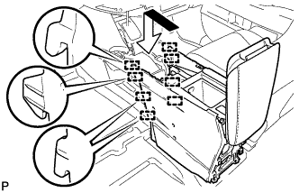
Engage the 8 guides as shown in the illustration.
-
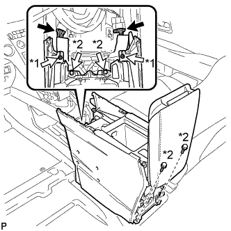
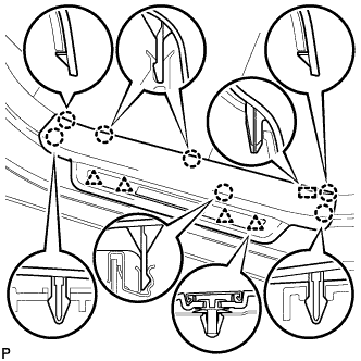
Text in Illustration *1 Screw *2 Bolt Install the rear console box assembly with the 2 screws and 4 bolts.
-
Connect each connector.
-
-
INSTALL MULTI-MEDIA INTERFACE ECU ASSEMBLY
-
Connect the connector.
-
Engage the clip and guide.
-
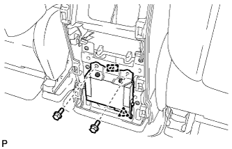
Install the multi-media interface ECU assembly with the 2 bolts.
- Torque:
- 6.0 N*m { 61 kgf*cm, 53 in.*lbf }
-
-
INSTALL CONSOLE REAR END PANEL SUB-ASSEMBLY
-
w/o Rear Seat Entertainment System:
-
Engage the 4 claws and 6 clips to install the console rear end panel sub-assembly.
-
-
w/ Rear Seat Entertainment System:
-
Connect each connector.
-
Engage the 4 claws and 6 clips to install the console rear end panel sub-assembly.
-
-
-
INSTALL NO. 2 CONSOLE BOX DUCT
-
Install the No. 2 console box duct with the 2 screws.
-
-
INSTALL UPPER CONSOLE PANEL SUB-ASSEMBLY
-
Engage the clamp.
-
Connect each connector.
-
Engage the 3 claws and 3 clips.
-
w/o Seat Heater System:
-
Connect the connector to the console box hole cover.
-
-
w/ Seat Heater System:
-
Connect the connector.
-
Engage the 4 claws to install the seat heater switch assembly.
-
-
Engage the 4 claws and 4 clips to install the upper console panel sub-assembly.
-
-
INSTALL SHIFT LEVER KNOB SUB-ASSEMBLY
-
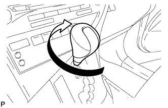
Turn the shift lever knob sub-assembly clockwise to install the shift lever knob sub-assembly.
-
-
INSTALL FRONT SEAT ASSEMBLY LH
Tech Tips
Refer to the instructions for Installation of the front seat assembly Click here.
-
INSTALL FRONT SEAT ASSEMBLY RH
Tech Tips
Perform the same procedure as for the LH side.
-
INSTALL SERVICE PLUG GRIP
Tech Tips
Refer to the instructions for Installation of the service plug grip Click here.
-
INSPECT SUSPENSION CONTROL SYSTEM (w/ Air Suspension)
-
INSPECT SRS WARNING LIGHT