STEERING ACTUATOR INSTALLATION
PROCEDURE
-
INSTALL STEERING SLIDING YOKE SUB-ASSEMBLY
-
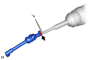
*a Matchmark Connect the steering sliding yoke sub-assembly to the steering actuator assembly.
Note
Align the matchmarks on the steering sliding yoke sub-assembly and steering actuator assembly.
-
Temporarily install the bolt.
-
-
HANDLING PRECAUTIONS FOR STEERING ACTUATOR ASSEMBLY (for LHD)
Note
-
Make sure that the No. 2 seal lip and boot do not turn outward while carrying or installing the steering actuator assembly.
-
If installing a new steering actuator assembly, make sure that the spiral center lock pin is securely inserted.
-
Do not use the steering actuator assembly if it has been dropped.
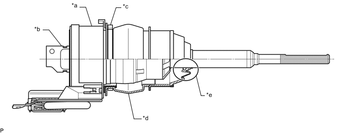
*a Spiral Case *b Sliding Yoke *c Actuator Clamp *d Boot *e No. 2 Seal Lip - - -
-
HANDLING PRECAUTIONS FOR STEERING ACTUATOR ASSEMBLY (for RHD)
Note
-
Make sure that the No. 2 seal lip and boot do not turn outward while carrying or installing the steering actuator assembly.
-
If installing a new steering actuator assembly, make sure that the spiral center lock pin is securely inserted.
-
Do not use the steering actuator assembly if it has been dropped.
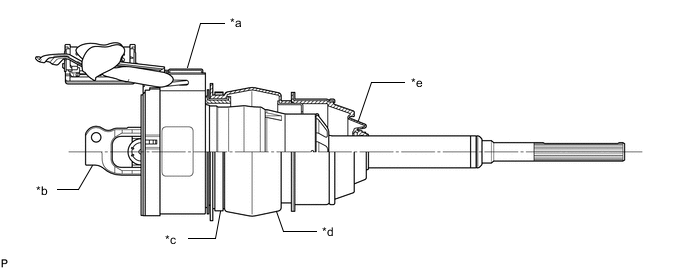
*a Spiral Case *b Sliding Yoke *c Actuator Clamp *d Boot *e No. 2 Seal Lip - - -
-
INSTALL STEERING ACTUATOR ASSEMBLY
-
If installing a new steering actuator assembly (for LHD):
-
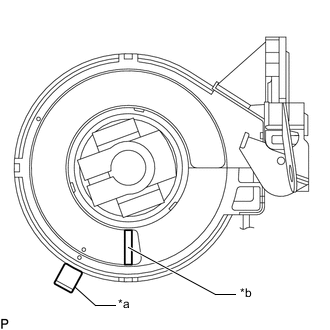
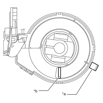
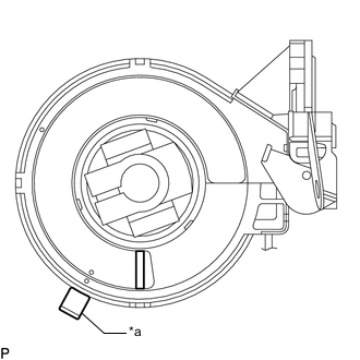
*a Center Lock Pin *b White Paint Make sure that the front wheel is facing straight ahead.
-
Install a new steering actuator assembly with the white paint on the surface of the spiral case facing downward.
Note
Do not pull out the center lock pin.
-
-
If installing a new steering actuator assembly (for RHD):
-
*a Center Lock Pin *b White Paint Make sure that the front wheel is facing straight ahead.
-
Install a new steering actuator assembly with the white paint on the surface of the spiral case facing downward.
Note
Do not pull out the center lock pin.
-
-
If reinstalling the removed steering actuator assembly (for LHD):
-
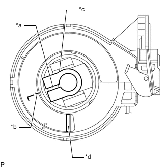
*a Slit *b Alignment Mark *c Sliding Yoke *d White Paint Make sure that the front wheels are facing straight ahead.
-
Slowly turn the spiral case clockwise until it locks.
-
Turn the spiral case two turns counterclockwise from the locked position.
-
Align the slit of the sliding yoke with the alignment mark (▲).
-
Install the steering actuator assembly with the white paint on the surface of the spiral case facing downward.
-
*a Matchmark Align the matchmarks on the steering actuator assembly and the No. 1 steering column hole cover sub-assembly.
Note
Do not turn the actuator body or spiral case.
-
-
If reinstalling the removed steering actuator assembly (for RHD):
-
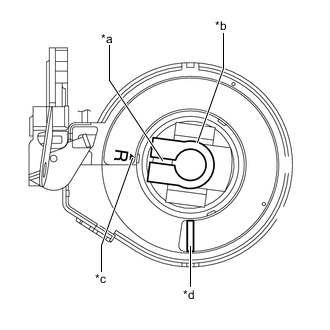
*a Slit *b Sliding Yoke *c Alignment Mark *d White Paint Make sure that the front wheel is facing straight ahead.
-
Slowly turn the spiral case clockwise until it locks.
-
Turn the spiral case two turns counterclockwise from the locked position.
-
Align the slit of the sliding yoke with the alignment mark (▲).
-
Install the steering actuator assembly with the white paint on the surface of the spiral case facing downward.
-
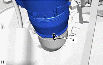
*a Matchmark Align the matchmarks on the steering actuator assembly and the No. 1 steering column hole cover sub-assembly.
Note
Do not turn the actuator body or spiral case.
-
-
Tighten the clamp.
-
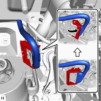
Connect the connector to the steering actuator assembly and move the lock as shown in the illustration.
-
If installing a new steering actuator assembly (for LHD):
-
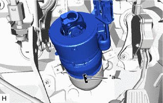
*a Center Lock Pin Pull out the center lock pin.
-
Tighten the actuator clamp.
-
-
If installing a new steering actuator assembly (for RHD):
-
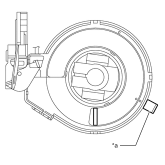
*a Center Lock Pin Pull out the center lock pin.
-
Tighten the actuator clamp.
-
-
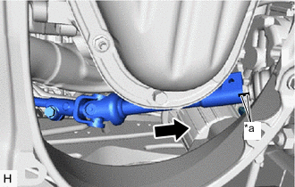
*a Matchmark Install the steering sliding yoke sub-assembly to the power steering link assembly.
Note
Align the matchmarks on the steering sliding yoke sub-assembly and power steering link assembly.
-
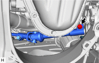
Install the bolt.
- Torque:
- 35.3 N*m { 360 kgf*cm, 26 ft.*lbf }
-
-
INSTALL LOWER MAIN SHAFT DUST COVER
-
Install the lower main shaft dust cover with the 2 bolts.
- Torque:
- 7.5 N*m { 76 kgf*cm, 66 in.*lbf }
-
-
INSTALL STEERING COLUMN ASSEMBLY
-
INSTALL NO. 2 ENGINE UNDER COVER (w/ No. 2 Engine Under Cover)
-
INSTALL FRONT SUSPENSION MEMBER BRACE (w/ No. 2 Engine Under Cover)
-
PERFORM VARIABLE GEAR RATIO STEERING SYSTEM CALIBRATION