FUEL LID LOCK CONTROL CABLE ASSEMBLY INSTALLATION

-
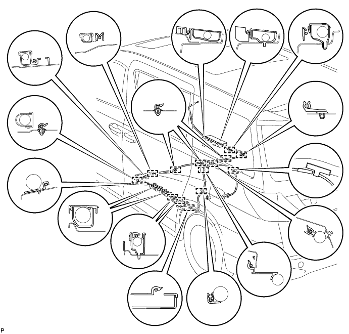
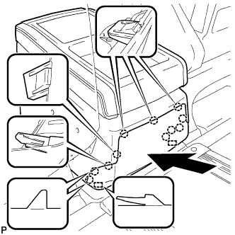
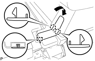
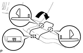
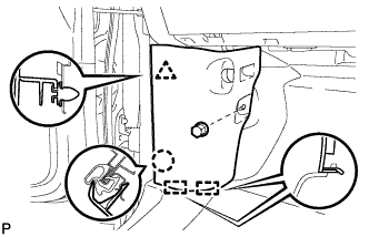
INSTALL FUEL FILLER OPENING LID LOCK SUB-ASSEMBLY (for RHD)
-
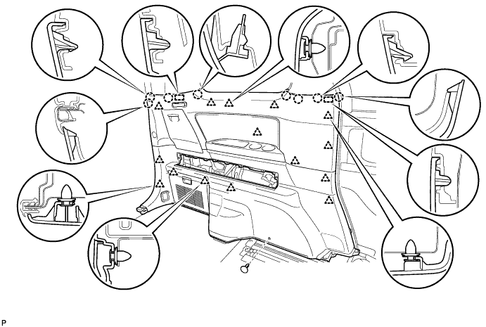
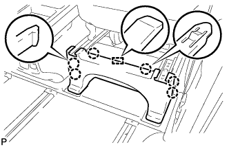
Engage the 14 clamps and install the fuel filler opening lid lock sub-assembly.
-
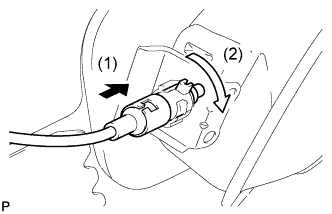
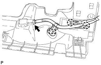
Connect the fuel lid lock control cable assembly as shown in the illustration.
-
-
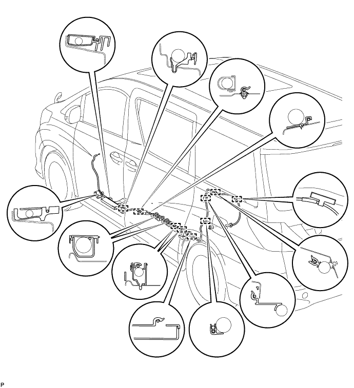
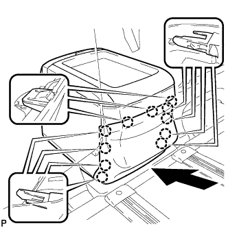
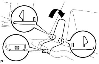
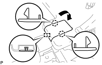
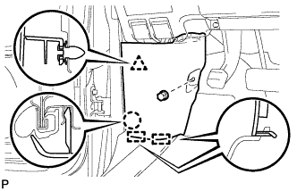
INSTALL FUEL FILLER OPENING LID LOCK SUB-ASSEMBLY (for LHD)
-
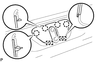
Engage the 9 clamps and install the fuel filler opening lid lock sub-assembly.
-
Connect the fuel lid lock control cable assembly as shown in the illustration.
-
-
INSTALL FUEL LID LOCK OPEN LEVER SUB-ASSEMBLY (for RHD)
-

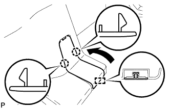
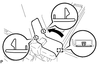
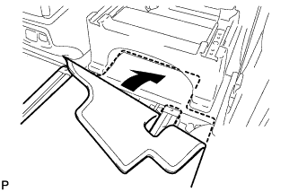
Connect the fuel filler opening lid lock sub-assembly to the fuel lid lock open lever sub-assembly.
-

Engage the 3 claws to install the fuel lid lock open lever sub-assembly.
-
-
INSTALL FUEL LID LOCK OPEN LEVER SUB-ASSEMBLY (for LHD)
-
Connect the fuel filler opening lid lock sub-assembly to the fuel lid lock open lever sub-assembly.
-
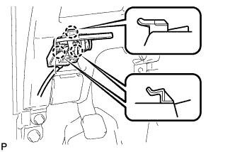
Engage the 3 claws to install the fuel lid lock open lever sub-assembly.
-
-
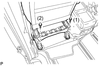
INSTALL NO. 1 INSTRUMENT PANEL UNDER COVER SUB-ASSEMBLY (for RHD)
-
Engage the 2 claws and DLC3.
-
Engage the clamp.
-
Connect the connector.
-

Engage the 2 claws and 2 guides.
Note
Make sure that the claws are fully engaged.
-
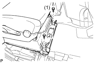
Install the No. 1 instrument panel under cover sub-assembly with the 2 screws <B>.
-
-
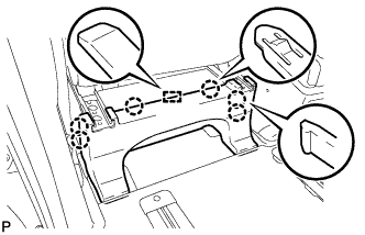
INSTALL NO. 1 INSTRUMENT PANEL UNDER COVER SUB-ASSEMBLY (for LHD)
-
Engage the clamp.
-
Connect each connector.
-

Engage the 2 claws and guide.
Note
Make sure that the claws are fully engaged.
-
Install the No. 1 instrument panel under cover sub-assembly with the 2 screws <B>.
-
-
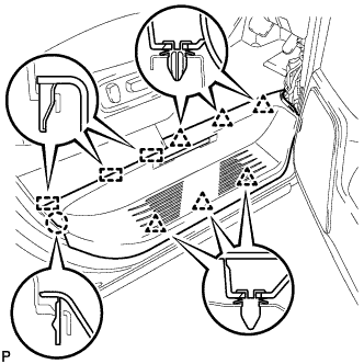
INSTALL REAR QUARTER TRIM PANEL ASSEMBLY LH
-
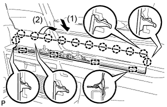
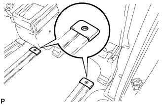
Engage the 2 guides, 8 claws and 15 clips, and install the rear quarter trim panel assembly LH.
-
Install the clip(A).
-
-
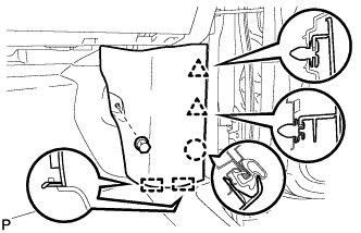
INSTALL DECK SIDE GARNISH LH
-
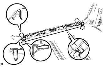
Engage the 4 guides and 12 claws to install the deck side garnish LH as shown in the illustration.
-
-
CONNECT REAR NO. 1 OUTER SEAT BELT ASSEMBLY LH (for 60/40 Split Seat Type)
Tech Tips
Use the same procedure for the RH side and LH side Click here.
-
INSTALL INNER LUGGAGE COMPARTMENT TRIM COVER LH (for 60/40 Split Seat Type)
Tech Tips
Use the same procedure for the RH side and LH side Click here.
-
INSTALL ROPE HOOK ASSEMBLY
Tech Tips
Use the same procedure for the RH side and LH side Click here.
-
INSTALL NO. 2 LUGGAGE COMPARTMENT TRIM HOOK
Tech Tips
Use the same procedure for the No. 2 luggage compartment trim hook and the No. 1 luggage compartment trim hook Click here.
-
INSTALL REAR NO. 2 SEAT ASSEMBLY LH
Tech Tips
Use the same procedure for the RH side and LH side Click here.
-
INSTALL NO. 1 SEAT TRACK LOCK PLATE COVER
Tech Tips
Use the same procedure for the RH side and LH side Click here.
-
INSTALL UPPER SEAT TRACK RAIL COVER LH
Tech Tips
Use the same procedure for the RH side and LH side Click here.
-
INSTALL RECLINING ADJUSTER RELEASE HANDLE LH
Tech Tips
Use the same procedure for the RH side and LH side Click here.
-
INSTALL BACK DOOR SCUFF PLATE
-
Engage the 2 guides, 4 clips and 4 claws to install the back door scuff plate.
-
-
INSTALL BACK DOOR STRIKER COVER
-
Engage the 2 guides and 4 claws to install the back door striker cover.
-
-
INSTALL LOWER CENTER PILLAR GARNISH LH
Tech Tips
Use the same procedure for the RH side and LH side Click here.
-
INSTALL NO. 2 ASSIST GRIP
Tech Tips
Use the same procedure for the RH side and LH side Click here.
-
INSTALL ASSIST GRIP PLUG
Tech Tips
Use the same procedure for the RH side and LH side Click here.
-
CONNECT FRONT SEAT OUTER BELT ASSEMBLY LH
Tech Tips
Use the same procedure for the RH side and LH side Click here.
-
INSTALL LAP BELT OUTER ANCHOR COVER
Tech Tips
Use the same procedure for the RH side and LH side Click here.
-
CONNECT NO. 1 SLIDE DOOR WEATHERSTRIP LH
-
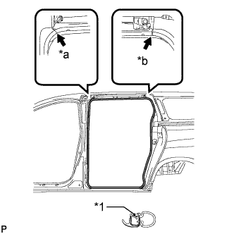
Text in Illustration *1 Alignment Mark *a White *b Light Blue Align the alignment marks on the weatherstrip with the protruding portions on the body indicated by the arrows in the illustration, and install the No. 1 slide door weatherstrip LH.
Note
After installation, check that the corners fit correctly.
-
-
INSTALL REAR DOOR SCUFF PLATE LH
Tech Tips
Use the same procedure for the RH side and LH side Click here.
-
INSTALL CONSOLE BOX ASSEMBLY
-
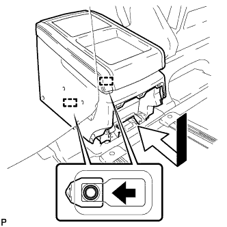
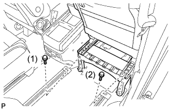
Engage the 2 guides as shown in the illustration.
-
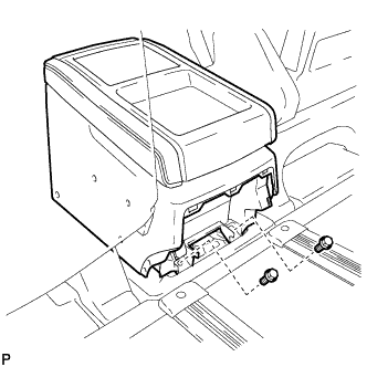
Install the console box assembly with the 2 bolts.
-
-
INSTALL CONSOLE REAR END PANEL
-
for Long Type:
-
w/ Power Outlet Socket:
-
Connect each connector.
-
-
Engage the 11 claws and 2 guides to install the console rear end panel as shown in the illustration.
Note
Make sure that the claws are fully engaged.
-
-
for Short Type:
-
Engage the 11 claws to install the console rear end panel as shown in the illustration.
Note
Make sure that the claws are fully engaged.
-
-
-
INSTALL FRONT SEAT ASSEMBLY (for Manual Seat Type RH Side)
-
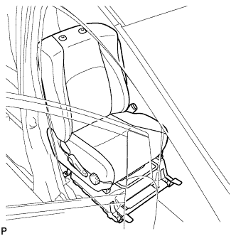
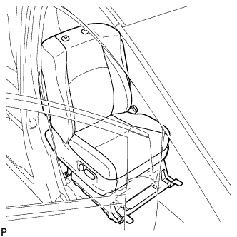
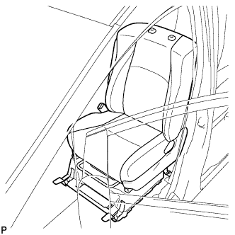
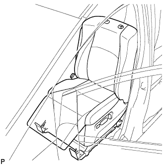
Place the front seat assembly in the cabin.
Note
Be careful not to damage the vehicle body.
-
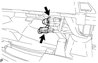
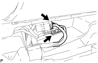
Connect each connector.
-
Temporarily install the front seat assembly with the 4 bolts.
-
Lift up the seat track adjusting handle and move the seat to the rearmost position.
-
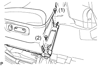
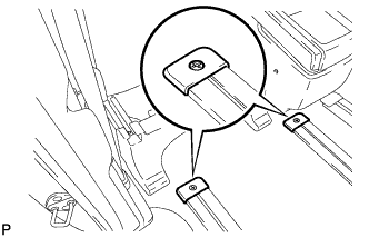
Tighten the 2 bolts on the front side of the seat.
- Torque:
- 39 N*m { 398 kgf*cm, 29 ft.*lbf }
Tech Tips
Tighten the bolts in the order indicated in the illustration.
-
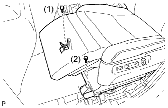
Engage the 2 claws and the guide to close the cover.
-
Engage the 2 claws and the guide to close the cover.
-
Lift up the seat track adjusting handle and move the seat to the foremost position.
-
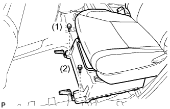
Tighten the 2 bolts on the rear side of the seat.
- Torque:
- 39 N*m { 398 kgf*cm, 29 ft.*lbf }
Tech Tips
Tighten the bolts in the order indicated in the illustration.
-
-
INSPECT FOR FRONT SEAT SLIDE ADJUSTER LOCKS (for Manual Seat Type RH Side)
-
During sliding operation of the front seat, check that the left and right adjusters move together smoothly and lock simultaneously. If the seat adjusters do not lock simultaneously, loosen the bolts securing the seat to adjust the adjuster position.
-
-
INSTALL FRONT SEAT HEADREST ASSEMBLY (for Manual Seat Type RH Side)
-
INSTALL FRONT SEAT LEG COVER RH (for Manual Seat Type RH Side)
-
Engage the 6 claws and the guide to install the front seat leg cover.
-
Install the floor carpet.
-
-
INSTALL NO. 3 FLOOR CARPET MOULDING (for Manual Seat Type RH Side)
-
Engage the 2 clips and install the 2 No. 3 floor carpet mouldings.
-
-
INSTALL FRONT SEAT ASSEMBLY (for Driver Side Power Seat)
-
Place the front seat assembly in the cabin.
Note
Be careful not to damage the vehicle body.
-
Connect the 2 connectors.
-
Connect the cable to the negative (-) battery terminal.
Note
When disconnecting the cable, some systems need to be initialized after the cable is reconnected Click here.
-
Temporarily install the front seat assembly with the 4 bolts.
-
Operate the slide and vertical power seat switch knob and move the seat to the rearmost position.
-
Tighten the 2 bolts on the front side of the seat.
- Torque:
- 39 N*m { 398 kgf*cm, 29 ft.*lbf }
Tech Tips
Tighten the bolts in the order indicated in the illustration.
-
Engage the 2 claws and guide to close the cover.
-
Engage the 2 claws and guide to close the cover.
-
Operate the slide and vertical power seat switch knob and move the seat to the foremost position.
-
Tighten the 2 bolts on the rear side of the seat.
- Torque:
- 39 N*m { 398 kgf*cm, 29 ft.*lbf }
Tech Tips
Tighten the bolts in the order indicated in the illustration.
-
The seat travel distance can be customized, this function is ON Click here.
-
-
INSTALL FRONT SEAT HEADREST ASSEMBLY (for Driver Side Power Seat)
-
INSTALL FRONT SEAT LEG COVER RH (for Driver Side Power Seat)
-
Engage the 6 claws and guide to install the front seat leg cover.
-
Install the floor carpet.
-
-
INSTALL NO. 3 FLOOR CARPET MOULDING (for Driver Side Power Seat)
-
Engage the 2 clips and install the 2 No. 3 floor carpet mouldings.
-
-
INSTALL FRONT SEAT ASSEMBLY (for Manual Seat Type LH Side)
-
Place the front seat assembly in the cabin.
Note
Be careful not to damage the vehicle body.
-
Connect the 2 connectors.
-
Temporarily install the front seat assembly with the 4 bolts.
-
Lift up the seat track adjusting handle and move the seat to the rearmost position.
-
Tighten the 2 bolts on the front side of the seat.
- Torque:
- 39 N*m { 398 kgf*cm, 29 ft.*lbf }
Tech Tips
Tighten the bolts in the order indicated in the illustration.
-
Engage the 2 claws and guide to close the cover.
-
Engage the 2 claws and guide to close the cover.
-
Lift up the seat track adjusting handle and move the seat to the foremost position.
-
Tighten the 2 bolts on the rear side of the seat.
- Torque:
- 39 N*m { 398 kgf*cm, 29 ft.*lbf }
Tech Tips
Tighten the bolts in the order indicated in the illustration.
-
-
INSPECT FOR FRONT SEAT SLIDE ADJUSTER LOCKS (for Manual Seat Type LH Side)
-
During sliding operation of the front seat, check that the left and right adjusters move together smoothly and lock simultaneously. If the seat adjusters do not lock simultaneously, loosen the bolts securing the seat to adjust the adjuster position.
-
-
INSTALL FRONT SEAT HEADREST ASSEMBLY (for Manual Seat Type LH Side)
-
INSTALL FRONT SEAT LEG COVER LH (for Manual Seat Type LH Side)
-
Engage the 6 claws and guide to install the front seat leg cover LH.
-
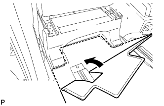
Install the floor carpet.
-
-
INSTALL NO. 3 FLOOR CARPET MOULDING (for Manual Seat Type LH Side)
-
Engage the 2 clips and install the 2 No. 3 floor carpet mouldings.
-
-
INSTALL FRONT SEAT ASSEMBLY (for Passenger Side Power Seat)
-
Place the front seat assembly in the cabin.
Note
Be careful not to damage the vehicle body.
-
Connect the 2 connectors.
-
Connect the cable to the negative (-) battery terminal.
Note
When disconnecting the cable, some systems need to be initialized after the cable is reconnected Click here.
-
Temporarily install the front seat assembly with the 4 bolts.
-
Operate the slide power seat switch knob and move the seat to the rearmost position.
-
Tighten the 2 bolts on the front side of the seat.
- Torque:
- 39 N*m { 398 kgf*cm, 29 ft.*lbf }
Tech Tips
Tighten the bolts in the order indicated in the illustration.
-
Engage the 2 claws and guide to close the cover.
-
Engage the 2 claws and guide to close the cover.
-
Operate the slide power seat switch knob and move the seat to the foremost position.
-
Tighten the 2 bolts on the rear side of the seat.
- Torque:
- 39 N*m { 398 kgf*cm, 29 ft.*lbf }
Tech Tips
Tighten the bolts in the order indicated in the illustration.
-
-
INSTALL FRONT SEAT HEADREST ASSEMBLY (for Passenger Side Power Seat)
-
INSTALL FRONT SEAT LEG COVER LH (for Passenger Side Power Seat)
-
Engage the 6 claws and guide to install the front seat leg cover LH.
-
Install the floor carpet.
-
-
INSTALL NO. 3 FLOOR CARPET MOULDING (for Passenger Side Power Seat)
-
Engage the 2 clips and install the 2 No. 3 floor carpet mouldings.
-
-
INSTALL FRONT DOOR SCUFF PLATE RH
-
Engage the 3 guides, claw and 6 clips to install the door scuff plate assembly RH.
-
-
INSTALL COWL SIDE TRIM BOARD RH (for RHD)
-

Engage the 2 guides, claw and clip to install the cowl side trim board RH.
-
Install the clip(A).
-
-
INSTALL COWL SIDE TRIM BOARD RH (for LHD)
-
Engage the 2 guides, claw and the 2 clips to install the cowl side trim board RH.
-
Install the clip(A).
-
-
INSTALL FRONT DOOR SCUFF PLATE LH
Tech Tips
Use the same procedure for the LH side and RH side.
-
INSTALL COWL SIDE TRIM BOARD LH (for RHD)
-
Engage the 2 guides, claw and clip to install the cowl side trim board LH.
-
Install the clip(A).
-
-
INSTALL COWL SIDE TRIM BOARD LH (for LHD)
-
Engage the 2 guides, claw and clip to install the cowl side trim board LH.
-
Install the clip(A).
-
-
CONNECT CABLE TO NEGATIVE BATTERY TERMINAL
Note
When disconnecting the cable, some systems need to be initialized after the cable is reconnected Click here.
-
INSPECT SRS WARNING LIGHT
-
INSPECT FRONT SEAT ASSEMBLY (for Power Seat)
for Driver Side: Click here
for Passenger Side: Click here
-
INSPECT SEAT BELT WARNING SYSTEM