ECD SYSTEM (w/ DPF), Diagnostic DTC:P20CD, P20D3

| DTC Code | DTC Name |
|---|---|
| P20CD | Open in Exhaust Aftertreatment Fuel Injector "A" Control Circuit |
| P20D3 | Open in Exhaust Aftertreatment Fuel Injector "B" Control Circuit |
DESCRIPTION
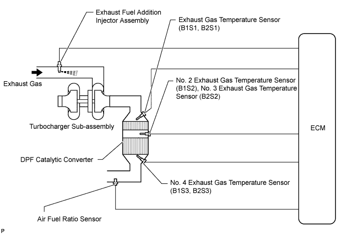
The exhaust fuel addition injector assembly is mounted on the exhaust port of the cylinder head, and low pressure fuel is supplied to the injector assembly by the feed pump in the fuel supply pump assembly. This injector adds fuel according to a control signal from the ECM.
This injector assembly is used for two different controls: PM forced regeneration and PM reduction.
During PM forced regeneration, the injector adds fuel to raise the catalyst temperature.
In the other control, the injector helps the air-fuel ratio become rich. As a result, PM in the exhaust gas will be reduced in response to the rich air-fuel ratio.
Tech Tips
-
For more information on the exhaust fuel addition injector assembly and DPF, refer to the following procedures Click here.
-
If P20CD or P20D3 is present, refer to the DTC table for Diesel Particulate Filter System Click here.
| DTC Detection Drive Pattern | DTC Detection Condition | Trouble Area |
|---|---|---|
| Engine switch on (IG) for 3 seconds | With the exhaust fuel addition injector off, the FIVO or FIVO2 output is high for 3 seconds. (1 trip detection logic) |
|
Tech Tips
DTC P200C, P200D, P20CF or P20D5 will be present if there is an open malfunction in the exhaust fuel addition injector circuit.
MONITOR DESCRIPTION
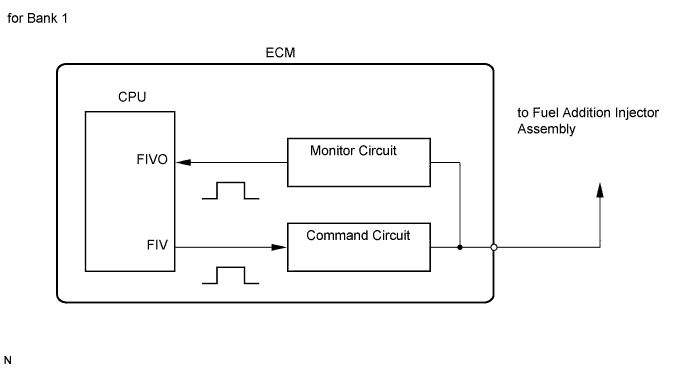
In order to detect abnormality in the fuel addition injector assembly, an internal CPU of the ECM monitors injection command (FIV and FIV2) signals and injection confirmation (FIVO and FIVO2) signals. The FIV and FIV2 signals are sent from the CPU to the exhaust fuel addition injector assembly via a drive circuit inside the ECM. The FIVO and FIVO2 signals, which are originally output current from the internal drive circuit of the ECM, are transmitted to the CPU via a monitor circuit. By receiving the FIVO and FIVO2 signals, the ECM judges that current has been applied to the exhaust fuel addition injector assembly.
These DTCs will be set if the ECM judges that the number of signals of the FIV and FIV2, and the FIVO and FIVO2 are inconsistent.
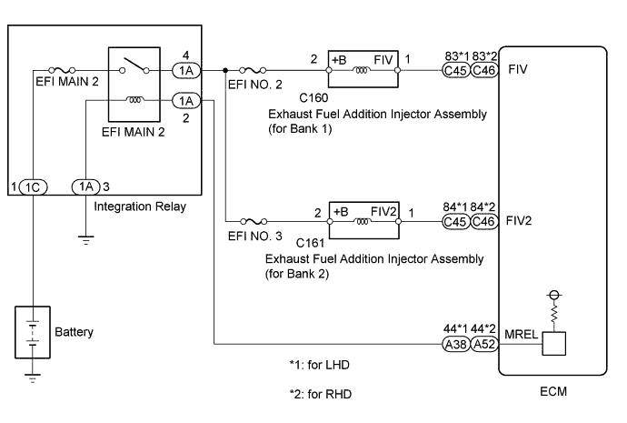
WIRING DIAGRAM
INSPECTION PROCEDURE
Note
-
Inspect the fuses of circuits related to this system before performing the following inspection procedure.
-
After replacing the ECM, the new ECM needs registration Click here and initialization Click here.
-
After replacing the fuel supply pump assembly, the ECM needs initialization Click here.
-
After replacing an injector assembly, the ECM needs registration Click here.
Tech Tips
Read freeze frame data using the GTS. Freeze frame data records the engine condition when malfunctions are detected. When troubleshooting, freeze frame data can help determine if the vehicle was moving or stationary, if the engine was warmed up or not, and other data from the time the malfunction occurred.
PROCEDURE
-
INSPECT EXHAUST FUEL ADDITION INJECTOR ASSEMBLY (RESISTANCE)
-
Inspect the exhaust fuel addition injector assembly (for bank 1 or bank 2) Click here.
NG 
REPLACE EXHAUST FUEL ADDITION INJECTOR ASSEMBLY Click here
OK 
-
-
CHECK TERMINAL VOLTAGE (POWER SOURCE)
-
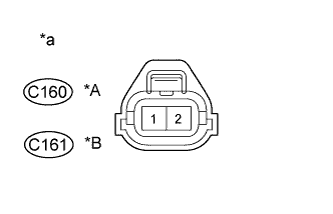
Text in Illustration *A for Bank 1 *B for Bank 2 *a Front view of wire harness connector
(to Exhaust Fuel Addition Injector Assembly)
Disconnect the exhaust fuel addition injector assembly connector.
-
Measure the voltage according to the value(s) in the table below.
Standard Voltage Tester Connection Switch Condition Specified Condition C160-2 - Body ground Engine switch on (IG) 11 to 14 V C161-2 - Body ground Engine switch on (IG) 11 to 14 V -
Reconnect the exhaust fuel addition injector assembly connector.
NG
REPAIR OR REPLACE HARNESS OR CONNECTOR Click here
OK
-
-
CHECK HARNESS AND CONNECTOR (EXHAUST FUEL ADDITION INJECTOR ASSEMBLY - ECM)
-
Disconnect the exhaust fuel addition injector assembly connector.
-
Disconnect the ECM connector.
-
Measure the resistance according to the value(s) in the table below.
Standard Resistance for LHD Tester Connection Condition Specified Condition C160-1 - C45-83 (FIV) Always Below 1 Ω C161-1 - C45-84 (FIV2) Always Below 1 Ω C160-1 or C45-83 (FIV) - Body ground Always 10 kΩ or higher C161-1 or C45-84 (FIV2) - Body ground Always 10 kΩ or higher Standard Resistance for RHD Tester Connection Condition Specified Condition C160-1 - C46-83 (FIV) Always Below 1 Ω C161-1 - C46-84 (FIV2) Always Below 1 Ω C160-1 or C46-83 (FIV) - Body ground Always 10 kΩ or higher C161-1 or C46-84 (FIV2) - Body ground Always 10 kΩ or higher -
Reconnect the exhaust fuel addition injector assembly connector.
-
Reconnect the ECM connector.
NG
REPAIR OR REPLACE HARNESS OR CONNECTOR Click here
OK
-
-
REPLACE ECM
-
Replace the ECM Click here.
NEXT
CONFIRM WHETHER MALFUNCTION HAS BEEN SUCCESSFULLY REPAIRED Click here
-
-
REPLACE EXHAUST FUEL ADDITION INJECTOR ASSEMBLY
-
When DTC P20CD is output:
Replace the exhaust fuel addition injector assembly (for bank 1) Click here.
-
When DTC P20D3 is output:
Replace the exhaust fuel addition injector assembly (for bank 2) Click here.
NEXT
-
-
PERFORM PM FORCED REGENERATION
-
Connect the GTS to the DLC3.
-
Turn the engine switch on (IG) and turn the GTS on.
-
Clear the DTCs Click here.
-
Perform PM forced regeneration Click here.
Tech Tips
When the exhaust fuel addition injector assembly is replaced, air may enter the fuel lines, leading to engine starting trouble. Therefore, perform forced regeneration and bleed the air from the fuel lines.
NEXT
CONFIRM WHETHER MALFUNCTION HAS BEEN SUCCESSFULLY REPAIRED Click here
-
-
REPAIR OR REPLACE HARNESS OR CONNECTOR
Tech Tips
If the voltage at the exhaust fuel addition injector assembly connector is not 11 to 14 V, repair or replace the harness and connector between the exhaust fuel addition injector assembly and EFI MAIN 2 relay (including the EFI No. 2 and EFI No. 3 fuses).
-
Repair or replace the harness or connector.
NEXT
-
-
CONFIRM WHETHER MALFUNCTION HAS BEEN SUCCESSFULLY REPAIRED
-
Connect the GTS to the DLC3.
-
Clear the DTCs Click here.
-
Drive the vehicle for 20 minutes.
Tech Tips
The exhaust gas temperature increases to 250°C (482°F) or higher after driving the vehicle for 20 minutes.
-
Enter the following menus: Engine and ECT / Trouble Codes.
-
Confirm that the DTC is not output again.
NEXT 
END
-