FUEL TANK INSTALLATION

-
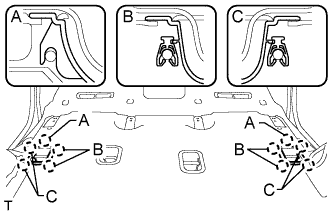
INSTALL NO. 1 FUEL TANK HEAT INSULATOR
-
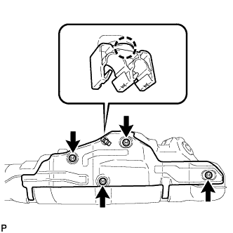
Install the heat insulator with the 4 clips.
-
Install the fuel tube clamp to the heat insulator.
-
-
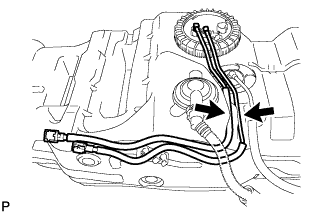
INSTALL FUEL TANK TO FILLER PIPE HOSE
-
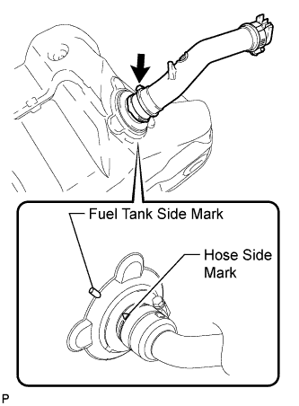
Install the fuel tank to filler pipe hose to the fuel tank as shown in the illustration.
Tech Tips
-
Align the fuel tank side mark with the hose side mark when installing the hose.
-
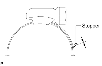
Tighten the hose clamp until the end of the hose clamp contacts the stopper as shown in the illustration.
-
-
-
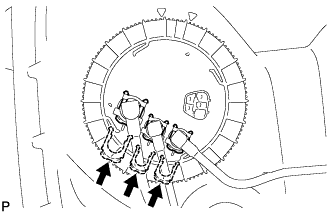
INSTALL FUEL SUCTION WITH PUMP AND GAUGE TUBE ASSEMBLY
-
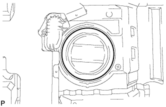
Apply a light coat of gasoline or grease to a new gasket, and install it to the fuel tank.
-
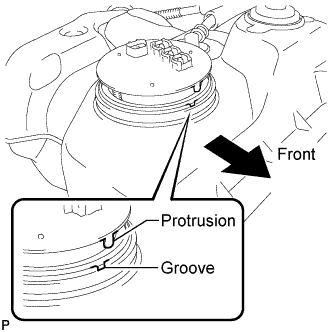
Install the fuel suction with pump and gauge tube into the fuel tank.
Note
Be careful not to bend the arm of the fuel sender gauge.
Tech Tips
Align the protrusion of the fuel suction with pump and gauge tube with the groove of the fuel tank.
-
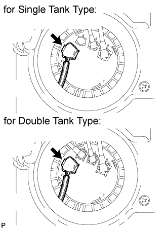
Put the retainer on the fuel tank. While holding the fuel suction with pump and gauge tube, tighten the retainer one complete turn by hand.
-
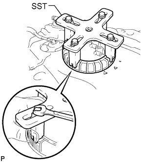
Set SST on the retainer.
- SST
- 09808-14030
Tech Tips
-
Hold the fuel suction tube assembly upright by hand to ensure that the fuel suction tube gasket is not moved out of position.
-
Securely attach the claws of SST to the protrusions of the retainer and fix SST in place.
-
Install SST while pressing the claws of SST against the retainer (toward the center of SST).
-
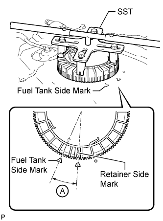
Using SST, tighten the retainer until the mark on the retainer is within range A on the fuel tank as shown in the illustration.
- SST
- 09808-14030
Tech Tips
Fit the tips of SST onto the ribs of the retainer.
-
-
INSTALL FUEL TANK MAIN TUBE SUB-ASSEMBLY AND FUEL TANK RETURN TUBE (for Single Tank Type)
-
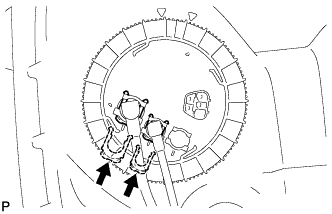
Install the 2 fuel tank tubes with the 2 tube joint clips.
Note
-
Check that there are no scratches or foreign objects on the connecting parts.
-
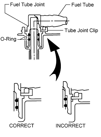
Check that the fuel tube joints are inserted securely.
-
Check that the tube joint clips are on the collars of the fuel tube joints.
-
After installing the tube joint clips, check that the fuel tube joints cannot be pulled off.
-
-
Install the 2 fuel tubes to the fuel tank.
-
-
INSTALL FUEL TANK MAIN TUBE SUB-ASSEMBLY, FUEL TANK RETURN TUBE AND NO. 2 FUEL MAIN TUBE SUB-ASSEMBLY (for Double Tank Type)
-
Install the 3 fuel tank tubes with the 3 tube joint clips.
Note
-
Check that there are no scratches or foreign objects on the connecting parts.
-
Check that the fuel tube joints are inserted securely.
-
Check that the tube joint clips are on the collars of the fuel tube joints.
-
After installing the tube joint clips, check that the fuel tube joints cannot be pulled off.
-
-
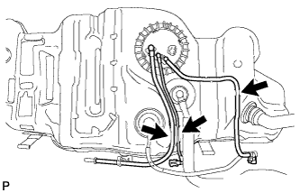
Install the 3 fuel tubes to the fuel tank.
-
-
INSTALL FUEL TANK SUB-ASSEMBLY
-
Set the fuel tank on a transmission jack.
-
Raise the transmission jack.
-
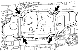
Install the 2 fuel tank bands with the 2 pins and 2 clips.
-
Connect the 2 fuel tank bands with the 2 bolts.
- Torque:
- 40 N*m { 408 kgf*cm, 30 ft.*lbf }
-
-
CONNECT FUEL TANK TO FILLER PIPE HOSE (for Single Tank Type)
-
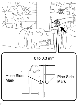
Connect the hose to the fuel tank filler pipe as shown in the illustration.
Tech Tips
-
Install the hose so that the distance between the fuel tank inlet pipe side mark and fuel tank to filler pipe hose side mark is 0 to 0.3 mm (0 to 0.0118 in.) as shown in the illustration.
-
Tighten the hose clamp until the end of the hose clamp contacts the stopper as shown in the illustration.
-
-
-
CONNECT FUEL TANK TO FILLER PIPE HOSE (for Double Tank Type)
-
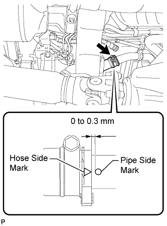
Connect the hose to the fuel tank filler pipe as shown in the illustration.
Tech Tips
-
Install the hose so that the distance between the fuel tank inlet pipe side mark and fuel tank to filler pipe hose side mark is 0 to 0.3 mm (0 to 0.0118 in.) as shown in the illustration.
-
Tighten the hose clamp until the end of the hose clamp contacts the stopper as shown in the illustration.
-
-
-
CONNECT FUEL TANK BREATHER TUBE (for Single Tank Type)
-
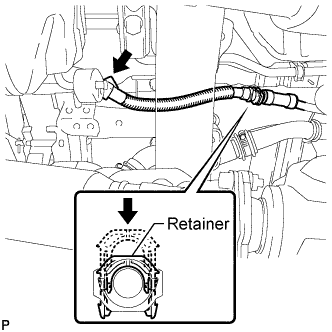
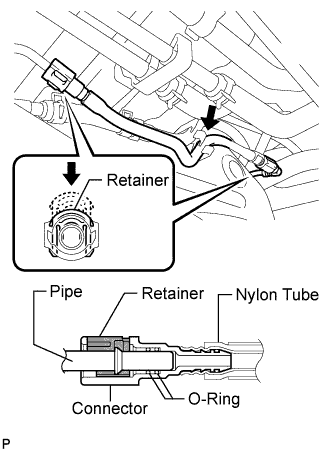
Connect the fuel tank breather tube to the filler pipe and push the retainer.
Tech Tips
Push the parts together firmly until a "click" sound is heard.
Note
-
Before installing the tube connectors to the pipes, check if there is any damage or foreign matter in the connectors.
-
After the connection, check if the connectors and pipes are securely connected by trying to pull them apart.
-
-
Attach the fuel tube clamp.
-
-
CONNECT FUEL TANK BREATHER TUBE (for Double Tank Type)
-
Connect the fuel tank breather tube to the filler pipe and push the retainer.
Tech Tips
Push the parts together firmly until a "click" sound is heard.
Note
-
Before installing the tube connectors to the pipes, check if there is any damage or foreign matter in the connectors.
-
After the connection, check if the connectors and pipes are securely connected by trying to pull them apart.
-
-
Attach the fuel tube clamp.
-
-
CONNECT NO. 2 FUEL TANK BREATHER TUBE (for Single Tank Type)
-
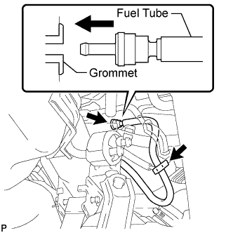
Connect the No. 2 fuel tank breather tube to the body.
Tech Tips
Make sure the No. 2 fuel tank breather tube is securely inserted into the grommet.
-
Attach the fuel tube clamp.
-
-
CONNECT NO. 2 FUEL TANK BREATHER TUBE (for Double Tank Type)
-
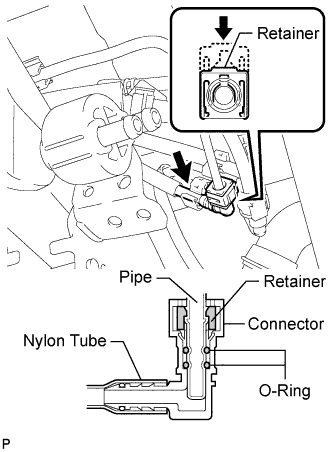
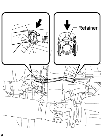
Connect the fuel tank breather tube and push the retainer.
Tech Tips
Push the parts together firmly until a "click" sound is heard.
Note
-
Before installing the tube connectors to the pipes, check if there is any damage or foreign matter in the connectors.
-
After the connection, check if the connectors and pipes are securely connected by trying to pull them apart.
-
-
Attach the fuel tube clamp.
-
-
CONNECT NO. 2 FUEL MAIN TUBE SUB-ASSEMBLY (for Double Tank Type)
-
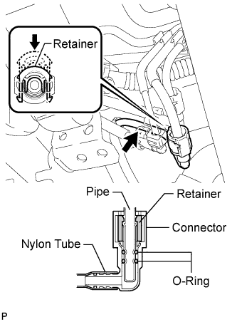
Connect the No. 2 fuel main tube and push the retainer.
Tech Tips
Push the parts together firmly until a "click" sound is heard.
Note
-
Before installing the tube connectors to the pipes, check if there is any damage or foreign matter in the connectors.
-
After the connection, check if the connectors and pipes are securely connected by trying to pull them apart.
-
-
Attach the fuel tube clamp.
-
-
CONNECT FUEL TANK MAIN TUBE SUB-ASSEMBLY
-
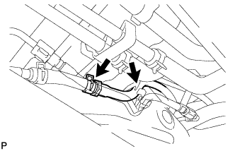
Connect the fuel tank main tube.
-
Attach the fuel tube clamp.
-
-
CONNECT FUEL TANK RETURN TUBE
-
Connect both ends of the fuel tank return tube and push the retainer.
Tech Tips
Push the parts together firmly until a "click" sound is heard.
Note
-
Before installing the tube connectors to the pipes, check if there is any damage or foreign matter in the connectors.
-
After the connection, check if the connectors and pipes are securely connected by trying to pull them apart.
-
-
Attach the fuel tube clamp.
-
-
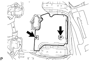
INSTALL NO. 1 FUEL TANK PROTECTOR SUB-ASSEMBLY
-
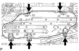
Install the tank protector with the 5 bolts.
- Torque:
- 20 N*m { 204 kgf*cm, 15 ft.*lbf }
-
-
INSTALL FUEL TANK CAP ASSEMBLY
-
INSTALL REAR FLOOR NO. 2 SERVICE HOLE COVER
-
Connect the fuel pump and fuel sender gauge connector.
-
Install the service hole cover with new butyl tape.
-
w/ Rear Air Conditioning System:
Install the air duct and 2 screws.
-
-
INSTALL FRONT FLOOR CARPET ASSEMBLY
-
INSTALL REAR AIR DUCT GUIDE (w/ Rear Air Conditioning System)
-
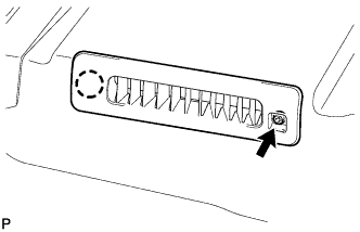
Attach the claw to install the guide.
-
Install the screw.
Tech Tips
Use the same procedures for both sides.
-
-
INSTALL AIR DUCT PLUG (w/ Rear Air Conditioning System)
-
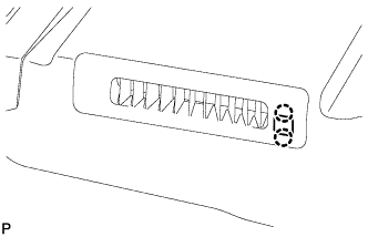
Attach the 2 claws to install the plug.
Tech Tips
Use the same procedures for both sides.
-
-
INSTALL FRONT QUARTER TRIM PANEL ASSEMBLY LH
-
w/ Sliding Roof:
Install the front quarter trim panel assembly LH Click here.
-
w/o Sliding Roof:
Install the front quarter trim panel assembly LH Click here.
-
-
INSTALL FRONT QUARTER TRIM PANEL ASSEMBLY RH
-
w/ Sliding Roof:
Install the front quarter trim panel assembly RH Click here.
-
w/o Sliding Roof:
Install the front quarter trim panel assembly RH Click here.
-
-
INSTALL REAR SEAT COVER CAP (w/ Rear No. 2 Seat, except Face to Face Seat Type)
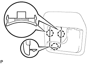
Tech Tips
Use the same procedure to install the rear seat cover cap on the other side.
-
Attach the 3 claws to install the rear seat cover cap.
-
-
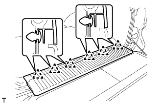
INSTALL REAR FLOOR MAT REAR SUPPORT PLATE
-
Attach the 6 clips to install the support plate.
-
-
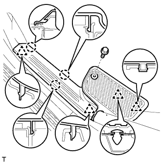
INSTALL REAR DOOR SCUFF PLATE LH
-
Attach the 3 claws and 4 clips to install the scuff plate.
-
Install the screw.
-
-
INSTALL REAR DOOR SCUFF PLATE RH
Tech Tips
Use the same procedures described for the LH side.
-
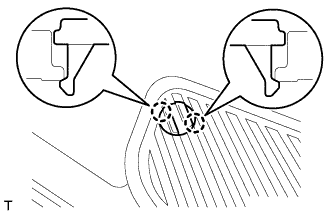
INSTALL REAR STEP COVER
Tech Tips
Use the same procedure to install the step cover on the other side.
-
Attach the 2 claws to install the step cover.
-
-
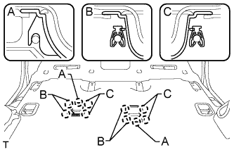
INSTALL REAR NO. 2 SEAT PROTECTOR
-
Attach the 10 claws to install the 2 seat protectors.
-
-
INSTALL REAR NO. 1 SEAT PROTECTOR
-
Attach the 10 claws to install the 2 seat protectors.
-
-
INSTALL REAR NO. 2 SEAT ASSEMBLY
-
for Face to Face Seat Type:
Install the rear No. 2 seat assembly Click here.
-
except Face to Face Seat Type:
Install the rear No. 2 seat assembly Click here.
-
-
INSTALL REAR NO. 1 SEAT ASSEMBLY RH (for 60/40 Split Seat Type 40 Side)
-
Install the rear No. 1 seat assembly RH Click here.
-
-
INSTALL REAR NO. 1 SEAT ASSEMBLY LH (for 60/40 Split Seat Type 60 Side)
-
Install the rear No. 1 seat assembly LH Click here.
-
-
BLEED AIR FROM FUEL SYSTEM
-

Using the hand pump mounted on the fuel filter cap, bleed air from the fuel system. Continue pumping until the pump resistance increases.
Note
-
The maximum hand pump pumping speed is 2 strokes per second.
-
The hand pump must be pushed with a full stroke during pumping.
-
When the fuel pressure at the supply pump inlet port reaches a saturated pressure, the hand pump resistance increases.
-
If pumping is interrupted during the air bleeding process, fuel in the fuel line may return to the fuel tank. Continue pumping until the hand pump resistance increases.
-
If the hand pump resistance does not increase despite consecutively pumping 200 times or more, there may be a fuel leak between the fuel tank and fuel filter, the hand pump may be malfunctioning, or the vehicle may have run out of fuel.
-
If air bleeding using the hand pump is incomplete, the common rail pressure does not rise to the pressure range necessary for normal use and the engine cannot be started.
-
-
Check if the engine starts.
Note
-
Even if air bleeding using the hand pump has been completed, the starter may need to be cranked for 10 seconds or more to start the engine.
-
Do not crank the engine continuously for more than 20 seconds. The battery may be discharged.
-
Use a fully-charged battery.
-
When the engine can be started, proceed to the next step.
-
If the engine cannot be started, bleed air again using the hand pump until the hand pump resistance increases (refer to the procedures above). Then start the engine.
-
-
Turn the engine switch off.
-
Connect the intelligent tester to the DLC3.
-
Turn the ignition switch ON (IG) and turn the intelligent tester on.
-
Clear the DTCs Click here.
-
Start the engine.*1
-
Enter the following menus: Powertrain / Engine and ECT / Active Test / Test the Fuel Leak.*2
-
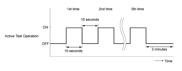
Perform the following test 5 times with on/off intervals of 10 seconds: Active Test / Test the Fuel Leak.*3
-
Allow the engine to idle for 3 minutes or more after performing the Active Test for the 5th time.
Tech Tips
When the Active Test "Test the Fuel Leak" is used to change the pump control mode, the actual fuel pressure inside the common rail drops below the target fuel pressure when the Active Test is off, but this is normal and does not indicate a pump malfunction.
-
Enter the following menus: Powertrain / Engine and ECT / DTC.
-
Read Current DTCs.
-
Clear the DTCs Click here.
Tech Tips
It is necessary to clear the DTCs as DTC P1604 or P1605 may be stored when air is bled from the fuel system after replacing or repairing fuel system parts.
-
Repeat steps *1 to *3.
-
Enter the following menus: Powertrain / Engine and ECT / DTC.
-
Read Current DTCs.
OK No DTCs are output.
-
-
CONNECT CABLE TO NEGATIVE BATTERY TERMINAL
Note
When disconnecting the cable, some systems need to be initialized after the cable is reconnected Click here.
-
Connect the cables to the negative (-) main battery and sub-battery terminals.
-
-
CHECK SRS WARNING LIGHT
-
Check the SRS warning light Click here.
-
-
ADD FUEL
-
INSPECT FOR FUEL LEAK
-
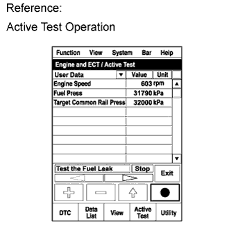
Perform Active Test.
-
Connect the intelligent tester to the DLC3.
-
Turn the ignition switch to ON.
-
Start the engine.
-
Turn the intelligent tester ON.
-
Enter the following menus: Powertrain / Engine and ECT / Active Test.
-
Perform the Active Test.
Tester Display Test Detail Control Range Diagnostic Note Test the Fuel Leak Pressurizes fuel inside common rail and checks for fuel leaks Stop/Start
-
The fuel inside the common rail is pressurized to the specified value and the engine speed increases to 2000 rpm when Start is selected.
-
The above conditions are preserved while Start is selected.
-
-
-