CAUTION / NOTICE / HINT
-
Use the same procedure for the RH side and LH side.
-
The procedure listed below is for the LH side.
PROCEDURE
- Click here
INSTALL FRONT AXLE HUB BEARING
-
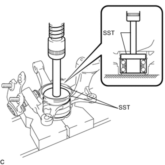
Using SST and a press, install a new front axle hub bearing to the steering knuckle.
09950-60020 09951-00810 09950-70010 09951-07100
-
- Click here
INSTALL FRONT DISC BRAKE DUST COVER
-
Install the front disc brake dust cover to the steering knuckle with the 4 bolts.
8.3 N*m 85 kgf*cm 73 in.*lbf
-
- Click here
INSTALL FRONT AXLE HUB SUB-ASSEMBLY
-
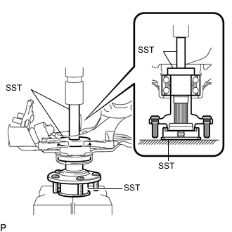
Using SST and a press, install the front axle hub sub-assembly to the steering knuckle.
09608-32010 09950-60010 09951-00610 09950-70010 09951-07100
-
- Click here
INSTALL FRONT AXLE HUB HOLE SNAP RING
-
Using snap ring pliers, install a new front axle hub hole snap ring.
-
- Click here
INSTALL FRONT NO. 1 WHEEL BEARING DUST DEFLECTOR
-
Set a new front No. 1 wheel bearing dust deflector to the steering knuckle while aligning the cutout for the speed sensor in the front No. 1 wheel bearing dust deflector with the hole of the steering knuckle.
-
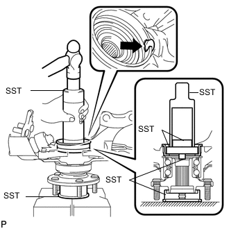
Using SST and a hammer, install the front No. 1 wheel bearing dust deflector.
09316-60011 09316-00011 09608-32010 09950-60010 09951-00500 09952-06010 09950-60020 09951-00810
-
- Click here
INSTALL FRONT AXLE ASSEMBLY
-
Install the front axle assembly to the front shock absorber with the 2 bolts and 2 nuts.
290 N*m 2957 kgf*cm 214 ft.*lbf Note:When installing the nuts, keep the bolts from rotating.
Tip:The bolt can be inserted in either direction, however, make sure that they are installed in the same direction.
-
- Click here
INSTALL FRONT DRIVE SHAFT ASSEMBLY
-
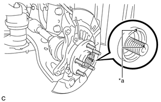
Align the matchmarks and install the front drive shaft assembly to the front axle hub sub-assembly.
Table 1. Text in Illustration *a Matchmark Note:Be careful not to damage the drive shaft boot or speed sensor rotor.
-
- Click here
CONNECT FRONT LOWER NO. 1 SUSPENSION ARM SUB-ASSEMBLY
-
Connect the front lower No. 1 suspension arm sub-assembly to the front lower ball joint assembly with the bolt and 2 nuts.
92 N*m 938 kgf*cm 68 ft.*lbf
-
- Click here
CONNECT TIE ROD ASSEMBLY
- Click here
INSTALL FRONT DISC
- Click here
INSTALL FRONT DISC BRAKE CALIPER ASSEMBLY
- Click here
INSTALL FRONT AXLE SHAFT NUT
-
Clean the threaded parts on the front drive shaft assembly and a new front axle shaft nut using a non-residue solvent.
Note:
-
Be sure to perform this work even when using a new front drive shaft assembly.
-
Keep the threaded parts free of oil and foreign matter.
-
-
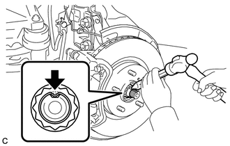
Using a socket wrench (30 mm), install the front axle shaft nut.
294 N*m 2998 kgf*cm 217 ft.*lbf Note:Stake the nut after inspecting for looseness and runout in the following steps.
Tip:Keep depressing the brake pedal to prevent the front drive shaft from rotating.
-
- Click here
SEPARATE FRONT DISC BRAKE CALIPER ASSEMBLY
- Click here
REMOVE FRONT DISC
- Click here
INSPECT FRONT AXLE HUB BEARING LOOSENESS
- Click here
INSPECT FRONT AXLE HUB RUNOUT
- Click here
INSTALL FRONT DISC
- Click here
INSTALL FRONT DISC BRAKE CALIPER ASSEMBLY
- Click here
INSTALL FRONT SPEED SENSOR
-
Install the front speed sensor and front flexible hose to the front shock absorber with the bolt and clamp.
19 N*m 192 kgf*cm 14 ft.*lbf Note:Do not twist the front speed sensor when installing it.
Tip:Install the speed sensor harness bracket first and then the front flexible hose.
-
Install the front speed sensor to the steering knuckle with the bolt.
8.5 N*m 87 kgf*cm 75 in.*lbf Note:Do not twist the front speed sensor when installing it.
-
- Click here
STAKE FRONT AXLE SHAFT NUT
-
Using a chisel and a hammer, stake the front axle shaft nut.
-
- Click here
INSTALL FRONT WHEEL
103 N*m 1049 kgf*cm 76 ft.*lbf - Click here
CONNECT CABLE TO NEGATIVE AUXILIARY BATTERY TERMINAL
-
Connect the cable to the negative (-) auxiliary battery terminal (Click here).
-
Connect the reservoir level switch connector.
-
Clear the DTCs (Click here).
-
- Click here
INSTALL FRONT OUTER COWL TOP PANEL SUB-ASSEMBLY (for RHD)
- Click here
INSTALL WINDSHIELD WIPER MOTOR AND LINK ASSEMBLY (for RHD)
Tip:Use the same procedure as for LHD (Click here).
- Click here
INSPECT AND ADJUST FRONT WHEEL ALIGNMENT
- Click here
CHECK FOR SPEED SENSOR SIGNAL