ENGINE ASSEMBLY REMOVAL
Info Added 2017-10-06 ![]()
CAUTION / NOTICE / HINT
The necessary procedures (adjustment, calibration, initialization, or registration) that must be performed after parts are removed, installed, or replaced during the engine assembly removal/installation are shown below.
| Replacement Part or Procedure | Necessary Procedure | Effect/Inoperative when not Performed | Link |
|---|---|---|---|
| Disconnect cable from negative battery terminal | Memorize steering angle neutral point | Lane departure alert system (w/ Steering Control) | |
| Simple intelligent parking assist system*1 | |||
| Toyota parking assist-sensor system (w/ Simple Intelligent Parking Assist System)*1 | |||
| Pre-collision syatem | |||
| Initialize back door lock | Power door lock control system | ||
| Drive the vehicle until stop and start control is permitted (approximately 5 to 60 minutes)*2 | Stop and start system | ||
|
Inspection After Repair |
|
|
| Replacement of CVT fluid | ATF thermal degradation estimate reset | The value of the Data List item "ATF thermal Degradation Estimate" is not estimated correctly | for K313 for K313F |
| Front wheel alignment adjustment | Perform the following procedures in the order shown:
|
|
-
*1: When performing learning using the GTS
-
*2: w/ Stop and start system
CAUTION:
-
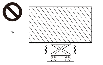
*a Heavy object exceeding the capacity of the engine lifter Because the weight of the engine with transaxle assembly is extremely heavy, make sure to follow the work procedures described in the repair manual.
-
If work is not performed according to the procedures described in the repair manual, there is a danger that the engine lifter could drop and components could fall down.
-
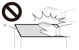
*a High temperature areas Do not touch the engine or exhaust manifold converter sub-assembly when they are hot.
-
Touching the engine or exhaust manifold converter sub-assembly when they are hot could result in burns.
-
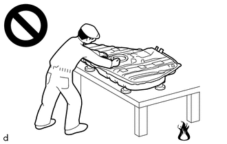
Never perform work on fuel system components near any possible ignition sources.
-
Vaporized fuel could ignite, resulting in a serious accident.
-
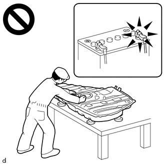
Do not perform work on fuel system components without first disconnecting the cable from the negative (-) battery terminal.
-
Sparks could cause vaporized fuel to ignite, resulting in a serious accident.
PROCEDURE
-
PRECAUTION
Note
After turning the ignition switch off, waiting time may be required before disconnecting the cable from the negative (-) battery terminal. Therefore, make sure to read the disconnecting the cable from the negative (-) battery terminal notices before proceeding with work.
-
RECOVER REFRIGERANT FROM REFRIGERATION SYSTEM (w/ Air Conditioning System)
-
for HFC-134a (R134a):
-
for HFO-1234yf (R1234yf):
-
-
DISCHARGE FUEL SYSTEM PRESSURE
-
ALIGN FRONT WHEELS FACING STRAIGHT AHEAD
-
DISCONNECT CABLE FROM NEGATIVE BATTERY TERMINAL
Note
When disconnecting the cable, some systems need to be initialized after the cable is reconnected.
-
REMOVE FRONT WHEELS
-
REMOVE NO. 1 ENGINE UNDER COVER
-
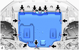
Remove the 4 bolts, 4 screws, 4 clips and No. 1 engine under cover from the vehicle.
-
-
REMOVE REAR ENGINE UNDER COVER LH
-
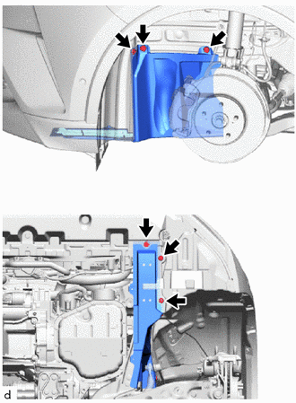
Remove the 6 clips and rear engine under cover LH from the vehicle.
-
-
REMOVE REAR ENGINE UNDER COVER RH
-
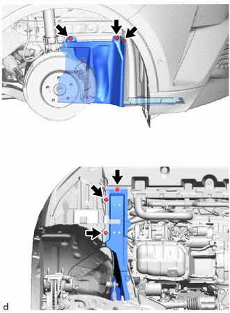
Remove the 6 clips and rear engine under cover RH from the vehicle.
-
-
DRAIN ENGINE OIL
-
DRAIN ENGINE COOLANT
-
DRAIN COOLANT (for Intercooler)
-
DRAIN CONTINUOUSLY VARIABLE TRANSAXLE FLUID (for CVT)
-
for 2WD:
-
for AWD:
-
-
DRAIN MANUAL TRANSAXLE OIL (for Manual Transaxle)
-
w/o Stop and Start System:
-
w/ Stop and Start System:
-
-
DRAIN TRANSFER OIL (for AWD)
-
REMOVE WINDSHIELD WIPER MOTOR AND LINK
-
REMOVE NO. 1 HEATER AIR DUCT SPLASH SHIELD SEAL
-
REMOVE WATER GUARD PLATE LH
-
REMOVE COWL BODY MOUNTING REINFORCEMENT LH
-
REMOVE COWL BODY MOUNTING REINFORCEMENT RH
-
REMOVE OUTER COWL TOP PANEL SUB-ASSEMBLY (for LHD)
-
REMOVE OUTER COWL TOP PANEL SUB-ASSEMBLY (for RHD)
-
REMOVE BATTERY
-
REMOVE RADIATOR COVER
-
REMOVE NO. 1 AIR CLEANER INLET
-
REMOVE AIR CLEANER CAP WITH AIR CLEANER HOSE
-
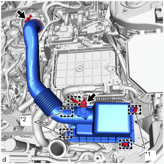
*1 Air Cleaner Cap Sub-assembly Clamp *2 Guide Disconnect the mass air flow meter connector.
-
Disengage the clamp from the air cleaner cap sub-assembly.
-
Disengage the 2 air cleaner cap sub-assembly clamps.
-
Disengage the 2 guides to separate the air cleaner cap sub-assembly from the air cleaner case sub-assembly.
-
Loosen the hose clamp and remove the air cleaner cap with air cleaner hose from the No. 1 inlet air duct sub-assembly.
-
-
REMOVE AIR CLEANER CASE SUB-ASSEMBLY
-
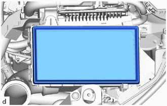
Remove the air cleaner filter element sub-assembly from the air cleaner case sub-assembly.
-
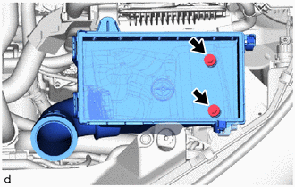
Remove the 2 bolts and air cleaner case sub-assembly from the vehicle.
-
-
REMOVE ECM
-
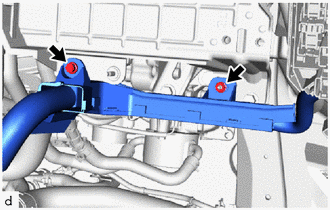
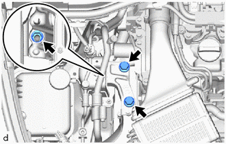
DISCONNECT WIRE HARNESS
-
Remove the 2 bolts to separate the engine wire from the vehicle.
-
Remove the bolt and nut to separate the engine wire from the battery clamp sub-assembly.
-
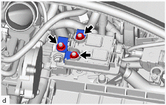
Remove the 3 nuts to separate the engine wire from the positive (+) battery terminal.
-
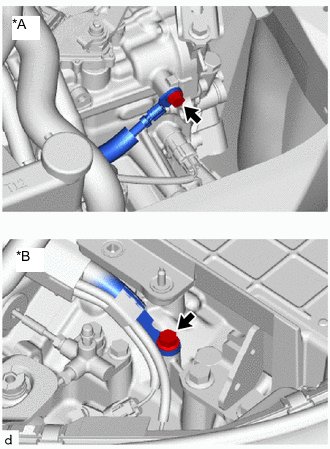
*A for CVT *B for Manual Transaxle Remove the bolt to separate the engine wire from the transaxle assembly.
-
-
REMOVE BATTERY CLAMP SUB-ASSEMBLY
-
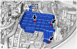
Disengage the clamp to separate the engine wire from the battery clamp sub-assembly.
-
Remove the 3 bolts and battery clamp sub-assembly from the vehicle.
-
-
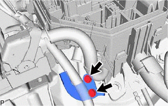
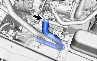
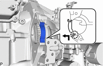
DISCONNECT NO. 1 RADIATOR HOSE
-
Slide the clip and disconnect the No. 1 radiator hose from the water outlet.
-
-
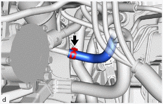
DISCONNECT NO. 2 RADIATOR HOSE
-
Slide the clip and disconnect the No. 2 radiator hose from the water inlet with thermostat sub-assembly.
-
-
DISCONNECT NO. 1 INTERCOOLER COOLING WATER HOSE
-
DISCONNECT NO. 4 INTERCOOLER COOLING WATER HOSE
-
DISCONNECT TRANSMISSION CONTROL CABLE ASSEMBLY (for CVT)
-
for 2WD:
-
for AWD:
-
-
DISCONNECT TRANSMISSION CONTROL CABLE ASSEMBLY (for Manual Transaxle)
-
w/o Stop and Start System:
-
w/ Stop and Start System:
-
-
DISCONNECT UNION TO CONNECTOR TUBE HOSE
-
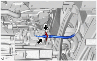
DISCONNECT FUEL VAPOR FEED HOSE
-
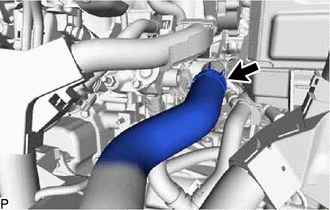
Slide the clip and disconnect the fuel vapor feed hose from the fuel vapor feed pipe.
-
-
DISCONNECT OUTLET HEATER WATER HOSE
-
DISCONNECT INLET HEATER WATER HOSE
-
DISCONNECT FUEL TUBE SUB-ASSEMBLY
-
DISCONNECT DISCHARGE HOSE SUB-ASSEMBLY (w/ Air Conditioning System)
-
DISCONNECT SUCTION HOSE SUB-ASSEMBLY (w/ Air Conditioning System)
-
SECURE STEERING WHEEL ASSEMBLY
-
REMOVE COLUMN HOLE COVER SILENCER SHEET
-
SEPARATE NO. 2 STEERING INTERMEDIATE SHAFT ASSEMBLY
-
SEPARATE NO. 1 STEERING COLUMN HOLE COVER SUB-ASSEMBLY
-
REMOVE FRONT FLOOR COVER LH (w/ Cover)
-
REMOVE FRONT FLOOR COVER RH (w/ Cover)
Tech Tips
Use the same procedure as for the LH side.
-
REMOVE FRONT FLOOR CENTER BRACE (for 2WD)
-
REMOVE FRONT FLOOR CENTER BRACE (for AWD)
-
REMOVE FRONT EXHAUST PIPE ASSEMBLY (TWC: Rear Catalyst) (for 2WD)
-
REMOVE NO. 2 CENTER EXHAUST PIPE ASSEMBLY (TWC: Rear Catalyst) (for AWD)
-
REMOVE FRONT EXHAUST PIPE ASSEMBLY (for AWD)
-
REMOVE PROPELLER WITH CENTER BEARING SHAFT ASSEMBLY (for AWD)
-
REMOVE FRONT DRIVE SHAFT ASSEMBLY
-
for TMC Made:
-
for TMMT Made:
-
-
REMOVE FLYWHEEL HOUSING UNDER COVER (for CVT)
-
for 2WD:
-
for AWD:
-
-
REMOVE DRIVE PLATE AND TORQUE CONVERTER ASSEMBLY SETTING BOLT (for CVT)
-
for 2WD:
-
for AWD:
-
-
DISCONNECT NO. 1 CLUTCH HOSE (for Manual Transaxle)
-
Using a 10 mm union nut wrench, disconnect the bleeder clutch release tube from the No. 1 clutch hose.
-
Remove the clip and disconnect the No. 1 clutch hose from the clutch flexible hose bracket.
-
-
REMOVE REAR SIDE RAIL REINFORCEMENT SUB-ASSEMBLY LH
-
REMOVE REAR SIDE RAIL REINFORCEMENT SUB-ASSEMBLY RH
Tech Tips
Use the same procedure as for the LH side.
-
REMOVE ENGINE ASSEMBLY WITH TRANSAXLE
-
Set the engine assembly with transaxle on an engine lifter.
Note
-
Using height adjustment attachments and plate lift attachments, keep the engine assembly with transaxle and front suspension crossmember sub-assembly level.
-
Do not perform any procedures while the engine assembly is suspended because doing so may cause the engine assembly to drop, resulting in injury. However, the engine assembly needs to be suspended when it is installed to or removed from an engine stand.
-
To prevent the engine assembly from unexpectedly moving, securely support the engine assembly until it is secured to an engine stand.
-
To prevent the oil pan sub-assembly from deforming, do not place any attachments under the oil pan sub-assembly of the engine assembly with transaxle.
-
-
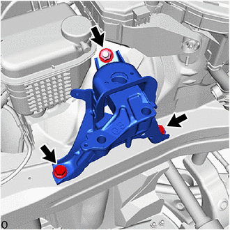
Remove the 2 bolts and nut and separate the engine mounting insulator sub-assembly RH from the engine mounting bracket RH.
-
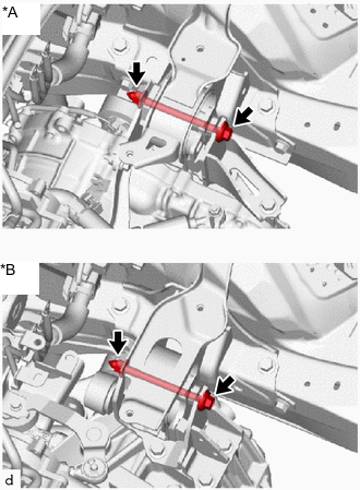
*A for CVT *B for Manual Transaxle Remove the bolt and nut and separate the engine mounting insulator LH from the engine mounting bracket LH.
Note
While holding the nut in place, loosen the bolt.
-
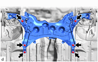
Remove the 6 bolts to separate the front suspension crossmember sub-assembly from the vehicle.
-
Operate the engine lifter and remove the engine assembly with transaxle from the vehicle.
Note
-
Make sure that the engine assembly with transaxle is clear of all wiring and hoses.
-
While lowering the engine assembly with transaxle from the vehicle, do not allow it to contact the vehicle.
-
-
-
REMOVE WIRE HARNESS CLAMP BRACKET
-
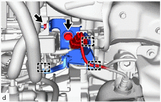
Disengage the 3 clamps.
-
Remove the nut to separate the engine wire from the wire harness clamp bracket.
-
Remove the bolt and wire harness clamp bracket from the cylinder head sub-assembly.
-
-
INSTALL ENGINE HANGERS
-
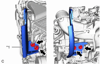
*1 No. 1 Engine Hanger *2 No. 2 Engine Hanger 
Bolt Install the No. 1 engine hanger and No. 2 engine hanger with the 4 bolts as shown in the illustration.
- Torque:
- 43 N*m { 438 kgf*cm, 32 ft.*lbf }
Tech Tips
No. 1 Engine Hanger 12281-47060 No. 2 Engine Hanger 12282-47030 Bolt 91552-81030 -
Using an engine sling device and engine lift, secure the engine assembly with transaxle.
Note
-
Pay attention to the angle of the sling device as the engine assembly or No. 1 engine hanger and No. 2 engine hanger may be damaged or deformed if the angle is incorrect.
-
Do not perform any procedures while the engine assembly is suspended because doing so may cause the engine assembly to drop, resulting in injury. However, the engine assembly needs to be suspended when it is installed to or removed from an engine stand.
-
-
-
REMOVE ENGINE MOUNTING INSULATOR LH
Tech Tips
Perform this procedure only when replacement of the engine mounting insulator LH is necessary.
-
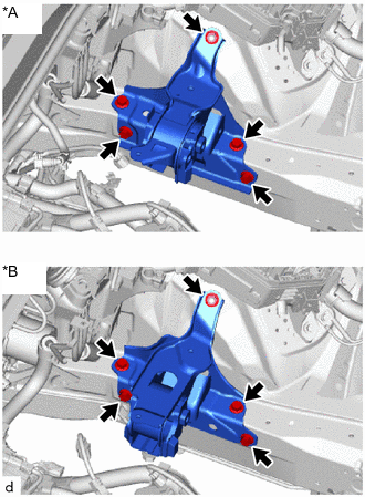
*A for CVT *B for Manual Transaxle Remove the 4 bolts, nut and engine mounting insulator LH from the vehicle.
-
-
REMOVE ENGINE MOUNTING INSULATOR SUB-ASSEMBLY RH (w/ Air Conditioning System)
Tech Tips
Perform this procedure only when replacement of the engine mounting insulator sub-assembly RH is necessary.
-
Remove the 2 bolts and No. 2 earth wire from the engine mounting insulator sub-assembly RH and vehicle.
-
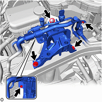
Remove the bolt, nut and disconnect the air conditioner tube and accessory.
-
Remove the 2 bolts, nut and engine mounting insulator sub-assembly RH from the vehicle.
-
-
REMOVE ENGINE MOUNTING INSULATOR SUB-ASSEMBLY RH (w/o Air Conditioning System)
Tech Tips
Perform this procedure only when replacement of the engine mounting insulator sub-assembly RH is necessary.
-
Remove the 2 bolts and No. 2 earth wire from the engine mounting insulator sub-assembly RH and vehicle.
-
Remove the 2 bolts, nut and engine mounting insulator sub-assembly RH from the vehicle.
-
-
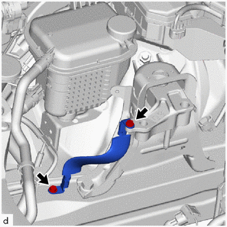
REMOVE WATER HOSE (for CVT)
-
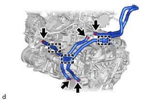
Disengage the 3 clamps from the engine assembly with transaxle.
-
Slide the 5 clips and remove the water hose from the engine assembly with transaxle.
-
-
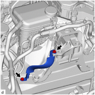
REMOVE WATER HOSE (for Manual Transaxle)
-
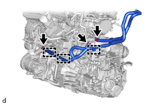
Disengage the 3 clamps from the engine assembly with transaxle.
-
Slide the 3 clips and remove the water hose from the engine assembly with transaxle.
-
-
REMOVE STARTER ASSEMBLY
-
for Denso Made with Stop and Start System:
-
for Denso Made without Stop and Start System:
-
for Valeo Made Cold Area Specification Vehicles:
-
for Valeo Made except Cold Area Specification Vehicles:
-
-
REMOVE FLYWHEEL HOUSING SIDE COVER
-
Remove the flywheel housing side cover from the cylinder block sub-assembly.
-
-
REMOVE ENGINE WIRE
-
Disconnect all the clamps and connectors and remove the engine wire from the engine assembly with transaxle.
-
-
REMOVE ENGINE ASSEMBLY (for CVT)
-
for 2WD:
-
for AWD:
-
-
REMOVE ENGINE ASSEMBLY (for Manual Transaxle)
-
w/o Stop and Start System:
-
w/ Stop and Start System:
-
-
REMOVE DRIVE PLATE AND RING GEAR SUB-ASSEMBLY (for CVT)
-
REMOVE CLUTCH DISC ASSEMBLY (for Manual Transaxle)
-
w/o Stop and Start System:
-
w/ Stop and Start System:
-
-
REMOVE FLYWHEEL SUB-ASSEMBLY (for Manual Transaxle)
-
REMOVE FAN AND GENERATOR V BELT
-
REMOVE V-RIBBED BELT TENSIONER ASSEMBLY
-
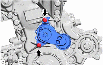
Remove the 2 bolts and V-ribbed belt tensioner assembly from the timing chain cover assembly.
-
-
REMOVE GENERATOR ASSEMBLY
-
for DENSO Made:
-
for VALEO Made:
-
-
REMOVE COMPRESSOR WITH PULLEY ASSEMBLY (w/ Air Conditioning System)
-
REMOVE NO. 1 IDLER PULLEY (w/o Air Conditioning System)
Tech Tips
Perform this procedure only when replacement of the No. 1 idler pulley is necessary.
-
Remove the bolt and No. 1 idler pulley with the 2 idler pulley cover plate from the idler pulley bracket.
-
-
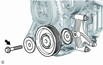
REMOVE NO. 1 IDLER PULLEY SUB-ASSEMBLY (w/o Air Conditioning System)
-
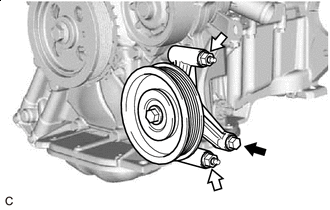
Bolt 
Nut Remove the bolt and 2 nuts.
-
Remove the No. 1 idler pulley sub-assembly.
-
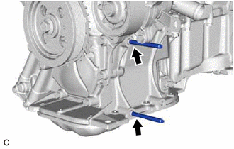
Using an E8 "TORX" socket wrench, remove the 2 stud bolts.
-
-
INSTALL ENGINE ASSEMBLY TO ENGINE STAND
-
Install the engine assembly to an engine stand.
-
-
REMOVE ENGINE HANGERS
-
Remove the 4 bolts, No. 1 engine hanger and No. 2 engine hanger.
-