CYLINDER HEAD GASKET REMOVAL
CAUTION / NOTICE / HINT
The necessary procedures (adjustment, calibration, initialization, or registration) that must be performed after parts are removed, installed, or replaced during the cylinder head gasket removal/installation are shown below.
| Replacement Part or Procedure | Necessary Procedures | Effects/Inoperative when not Performed | Link |
|---|---|---|---|
| Replacement of injector assembly |
|
Engine starting | |
|
Perform initialization | - | |
| Replacement of timing belt | Mode reset operation |
|
CAUTION:
To prevent burns, do not touch the engine, exhaust manifold or other high temperature components while the engine is hot.

Note
-
When replacing the parts in the following chart (A), replace the No. 1 injection pipe sub-assembly, No. 2 injection pipe sub-assembly, No. 3 injection pipe sub-assembly, No. 4 injection pipe sub-assembly and/or fuel inlet pipe sub-assembly with new ones.
Replaced Parts (A) Pipes Requiring New Replacement
-
Injector assembly (including shuffling the injector assemblies between the cylinders)
-
Common rail assembly
-
Cylinder head sub-assembly
-
No. 1 injection pipe sub-assembly
-
No. 2 injection pipe sub-assembly
-
No. 3 injection pipe sub-assembly
-
No. 4 injection pipe sub-assembly
-
Supply pump assembly
-
Common rail assembly
-
Cylinder block sub-assembly
-
Cylinder head sub-assembly
-
Cylinder head gasket
-
Timing Gear Case Assembly
Fuel inlet pipe sub-assembly -
-
After removing the No. 1 injection pipe sub-assembly, No. 2 injection pipe sub-assembly, No. 3 injection pipe sub-assembly, No. 4 injection pipe sub-assembly and fuel inlet pipe sub-assembly, clean them with a brush and compressed air.
PROCEDURE
-
PRECAUTION
Note
After turning the ignition switch off, waiting time may be required before disconnecting the cable from the battery terminal. Therefore, make sure to read the disconnecting the cable from the battery terminal notice before proceeding with work.
-
DISCONNECT CABLE FROM NEGATIVE BATTERY TERMINAL
Note
When disconnecting the cable, some systems need to be initialized after the cable is reconnected.
-
DRAIN ENGINE OIL
-
REMOVE INTAKE MANIFOLD
-
REMOVE GLOW PLUG ASSEMBLY
-
REMOVE INJECTOR ASSEMBLY
-
REMOVE COMMON RAIL ASSEMBLY
-
REMOVE EXHAUST MANIFOLD WITH TURBOCHARGER
-
REMOVE FAN SHROUD
-
DISCONNECT COOLER COMPRESSOR ASSEMBLY
-
REMOVE NO. 1 COMPRESSOR MOUNTING BRACKET
-
REMOVE NO. 1 TIMING BELT COVER
-
REMOVE TIMING BELT
-
REMOVE NO. 1 TIMING BELT IDLER SUB-ASSEMBLY
-
REMOVE CAMSHAFT TIMING PULLEY
-
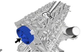
Remove the bolt of the camshaft timing pulley while holding the camshaft with a wrench.
Note
Make sure to remove the bolt of the camshaft timing pulley with the timing belt not installed.
-
Remove the camshaft timing pulley from the intake camshaft sub-assembly.
-
-
REMOVE NO. 2 TIMING BELT COVER
-
Remove the 4 bolts, nut and No. 2 timing belt cover from the cylinder head sub-assembly and timing gear cover.
-
-
REMOVE CAMSHAFT SUB-ASSEMBLY
-
REMOVE VALVE LIFTER
-
REMOVE CYLINDER HEAD SUB-ASSEMBLY
-
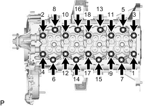
Uniformly loosen the 18 cylinder head set bolts in several passes in the sequence shown in the illustration. Then remove the 18 cylinder head set bolts and 18 washers.
Note
Cylinder head warpage or cracking could result from removing bolts in the incorrect order.
-
Lift the cylinder head sub-assembly from the dowels on the cylinder block sub-assembly, and place the cylinder head sub-assembly on wooden blocks on a bench.
Note
Be careful not to damage the contact surfaces of the cylinder head sub-assembly and cylinder block sub-assembly.
Tech Tips
If the cylinder head sub-assembly is difficult to lift, use a screwdriver to pry between the cylinder head sub-assembly and cylinder block sub-assembly.
-
-
REMOVE CYLINDER HEAD GASKET