STEERING COLUMN ASSEMBLY INSTALLATION
PROCEDURE
-
ALIGN FRONT WHEELS FACING STRAIGHT AHEAD
-
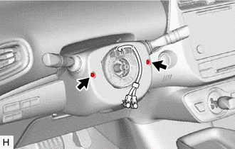
INSTALL STEERING COLUMN ASSEMBLY (for RHD)
Note
Make sure that the wire harness is not interfering with the steering column assembly.
-
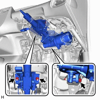
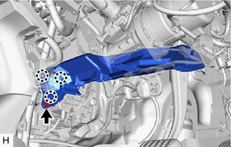
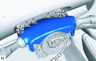
Install the steering column assembly with the bolt and 2 nuts.
- Torque:
- 36 N*m { 367 kgf*cm, 27 ft.*lbf }
-
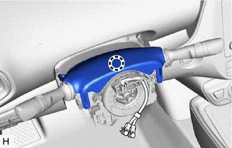
Connect each connector and engage each clamp to the steering column assembly.
-
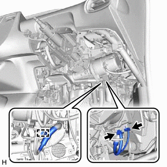
Engage the clamp.
-
Connect the 2 connectors.
-
-
INSTALL STEERING COLUMN ASSEMBLY (for LHD)
-
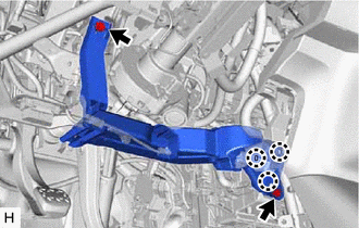
Install the steering column assembly with the bolt and 2 nuts.
- Torque:
- 36 N*m { 367 kgf*cm, 27 ft.*lbf }
-
Connect each connector and engage each clamp to the steering column assembly.
-
Engage the clamp.
-
Connect the 2 connectors.
-
-
INSTALL NO. 2 STEERING INTERMEDIATE SHAFT ASSEMBLY
-
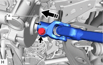
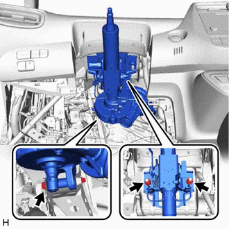
*a Matchmark 
Install in this direction Align the matchmarks on the No. 2 steering intermediate shaft assembly and steering column assembly.
-
Install the No. 2 steering intermediate shaft assembly to the steering column assembly.
-
Install the bolt.
- Torque:
- 64 N*m { 653 kgf*cm, 47 ft.*lbf }
-
-
CONNECT NO. 2 STEERING INTERMEDIATE SHAFT ASSEMBLY
-
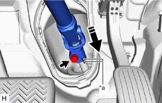
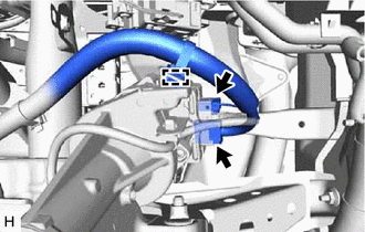
*a Matchmark Connect in this direction Align the matchmarks on the No. 2 steering intermediate shaft assembly and steering gear assembly.
-
Connect the No. 2 steering intermediate shaft assembly to the steering gear assembly.
-
Install the bolt.
- Torque:
- 64 N*m { 653 kgf*cm, 47 ft.*lbf }
-
-
INSTALL COLUMN HOLE COVER SILENCER SHEET
-
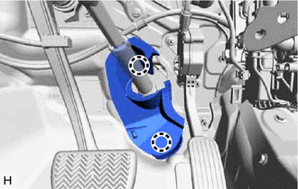
Engage the 2 claws to install the column hole cover silencer sheet.
-
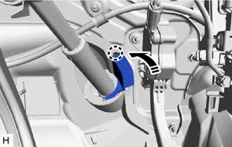
Engage the claw to close the column hole cover silencer sheet.
-
-
INSTALL STOP LIGHT SWITCH ASSEMBLY
-
INSTALL NO. 2 AIR DUCT (for RHD)
-
Engage the 3 claws to install a new No. 2 air duct.
-
Install the bolt.
- Torque:
- 9.8 N*m { 100 kgf*cm, 87 in.*lbf }
-
-
INSTALL PARKING BRAKE MOUNTING BRACKET (for RHD)
-
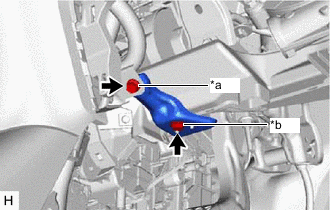
*a Bolt *b Screw Install the parking brake mounting bracket with the bolt and screw.
- Torque:
- Bolt
- 10 N*m { 102 kgf*cm, 7 ft.*lbf }
-
-
INSTALL NO. 1 AIR DUCT (for LHD)
-
Engage the 3 claws to install a new No. 1 air duct.
-
Install the 2 bolts.
- Torque:
- 9.8 N*m { 100 kgf*cm, 87 in.*lbf }
-
-
INSTALL FRONT NO. 1 CONSOLE BOX INSERT
-
INSTALL LOWER CENTER INSTRUMENT CLUSTER FINISH PANEL SUB-ASSEMBLY
-
INSTALL REAR CONSOLE BOX ASSEMBLY
-
INSTALL LOWER NO. 1 INSTRUMENT PANEL AIRBAG ASSEMBLY
-
INSTALL TURN SIGNAL SWITCH ASSEMBLY WITH SPIRAL CABLE SUB-ASSEMBLY
Note
-
Do not replace the spiral cable with sensor sub-assembly with the auxiliary battery connected and the power switch on (IG).
-
Do not rotate the spiral cable with sensor sub-assembly without the steering wheel assembly installed with the auxiliary battery connected and the power switch on (IG).
-
Ensure that the steering wheel assembly is installed and aligned straight when inspecting the steering sensor.
-
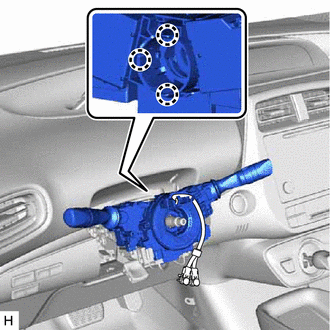
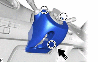
Engage the 3 claws to install the turn signal switch assembly with spiral cable sub-assembly to the steering column assembly.
-
Connect each connector to the turn signal switch assembly with spiral cable sub-assembly.
-
-
INSTALL UPPER STEERING COLUMN COVER
-
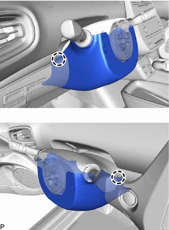
Engage the 2 claws and 4 clips to connect the upper steering column cover.
-
Engage the claw to install the upper steering column cover.
-
-
INSTALL LOWER STEERING COLUMN COVER SUB-ASSEMBLY
Note
If the lower steering column cover sub-assembly is installed in the incorrect order, the parts may break.
-
Install in this Direction Engage the 3 claws as shown in the illustration.
-
Engage the 2 claws.
-
Install the 2 screws.
- Torque:
- 2.0 N*m { 20 kgf*cm, 18 in.*lbf }
-
-
ALIGN FRONT WHEELS FACING STRAIGHT AHEAD
-
INSPECT AND ADJUST SPIRAL CABLE WITH SENSOR SUB-ASSEMBLY
-
INSTALL STEERING WHEEL ASSEMBLY
-
CHECK STEERING WHEEL CENTER POINT
-
INSTALL HORN BUTTON ASSEMBLY
-
TORQUE SENSOR ZERO POINT CALIBRATION