PARKING BRAKE PEDAL(for LHD) INSTALLATION
PROCEDURE
-
INSTALL PARKING BRAKE PEDAL ASSEMBLY
-
Pass the No. 1 parking brake cable assembly through the parking brake pedal assembly.
-
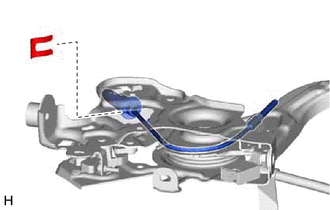
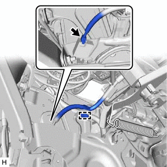
Install a new clip to the No. 1 parking brake cable assembly.
-
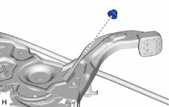
Temporarily install a new No. 1 wire adjusting nut to the No. 1 parking brake cable assembly.
Note
If the No. 1 wire adjusting nut has been removed from the No. 1 parking brake cable assembly, replace the No. 1 wire adjusting nut with a new one.
-
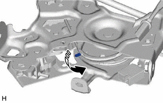
Bend the parking brake pedal assembly claw.
-
-
CONNECT PARKING BRAKE PEDAL ASSEMBLY
-
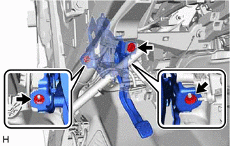
Install the parking brake pedal assembly to the vehicle body with the bolt and 2 nuts.
- Torque:
- Bolt
- 15 N*m { 153 kgf*cm, 11 ft.*lbf }
- Nut
- 15.5 N*m { 158 kgf*cm, 11 ft.*lbf }
-
Connect the parking brake switch connector.
-
Engage the clamp.
-
-
CONNECT NO. 1 PARKING BRAKE CABLE ASSEMBLY
-
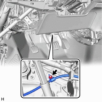
Install the No. 1 parking brake cable assembly with the bolt.
- Torque:
- 7.5 N*m { 76 kgf*cm, 66 in.*lbf }
-
-
INSTALL BRAKE PEDAL STROKE SENSOR ASSEMBLY
-
CONNECT CABLE TO NEGATIVE AUXILIARY BATTERY TERMINAL
Note
When disconnecting the cable, some systems need to be initialized after the cable is reconnected.
-
ADJUST BRAKE PEDAL STROKE SENSOR ASSEMBLY
-
INSPECT PARKING BRAKE PEDAL TRAVEL
-
ADJUST PARKING BRAKE PEDAL TRAVEL
-
INSPECT BRAKE WARNING LIGHT
-
INSTALL LOWER INSTRUMENT PANEL FINISH PANEL ASSEMBLY
-
CONNECT HOOD LOCK CONTROL LEVER SUB-ASSEMBLY
-
INSTALL INSTRUMENT CLUSTER FINISH PANEL GARNISH ASSEMBLY
-
INSTALL INSTRUMENT PANEL FINISH PANEL END LH
-
INSTALL COWL SIDE TRIM BOARD LH
-
INSTALL FRONT DOOR SCUFF PLATE LH
-
INSTALL NO. 1 AIR DUCT
-
INSTALL FRONT NO. 2 CONSOLE BOX INSERT
-
INSTALL FRONT NO. 1 CONSOLE BOX INSERT
-
INSTALL LOWER CENTER INSTRUMENT CLUSTER FINISH PANEL SUB-ASSEMBLY
-
INSTALL REAR CONSOLE BOX ASSEMBLY
-
INSTALL NO. 1 INSTRUMENT PANEL UNDER COVER SUB-ASSEMBLY
-
PERFORM INITIALIZATION AND CALIBRATION
Perform linear solenoid valve offset learning, ABS holding solenoid valve learning, brake pedal stroke sensor assembly zero point calibration and system information memorization: Click here
-
CHECK AND CLEAR DTC