IMMOBILISER SYSTEM(w/o Entry and Start System) Engine does not Start but Initial Combustion Occurs
DESCRIPTION
If the key ID codes of the key and transponder key ECU assembly match, the immobiliser system is unset and the engine start permission signal is sent to the ECM. When the ID codes of the transponder key ECU assembly and ECM match, the engine starts.
WIRING DIAGRAM
-
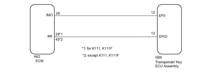
1. for 3ZR Series Engine
-
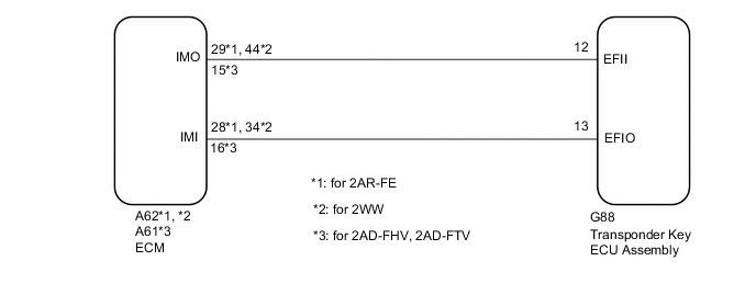
2. except 3ZR Series Engine
CAUTION / NOTICE / HINT
Note
-
If the transponder key ECU assembly or ECM is replaced, refer to the Service Bulletin.
-
When using the GTS with the vehicle ignition switch off, connect the GTS to the vehicle and turn a courtesy light switch on and off at intervals of 1.5 seconds or less until communication between the GTS and the vehicle begins. Then select the Model Code "KEY REGIST" under manual mode and enter the following menus: Body Electrical / Immobiliser. While using the GTS, periodically turn a courtesy light switch on and off at intervals of 1.5 seconds or less to maintain communication between the GTS and the vehicle.
PROCEDURE
-
CLEAR DTC
-
Clear the DTCs.
Powertrain > Engine and ECT > Clear DTCs
Powertrain > Engine > Clear DTCs
Body Electrical > Immobiliser > Clear DTCs
Body Electrical > Telematics > Clear DTCsResult Proceed to NEXT
NEXT 
-
-
CHECK FOR DTC
-
Check for DTCs.
Powertrain > Engine and ECT > Trouble Codes
Powertrain > Engine > Trouble Codes
Body Electrical > Immobiliser > Trouble Codes
Body Electrical > Telematics > Trouble CodesTech Tips
Before checking for DTCs, perform the "DTC Output Confirmation Operation" procedure.
Result Proceed to DTCs are not output (for Gasoline) DTCs are not output (for Diesel) DTCs are output
DTCs are not output (for Diesel) 
GO TO STEP 4 Click here
DTCs are output 
GO TO DIAGNOSTIC TROUBLE CODE CHART Click here
DTCs are not output (for Gasoline)
-
-
READ VALUE USING GTS (IMMOBILISER FUEL CUT)
-
Connect the GTS to the DLC3.
-
Turn the ignition switch to ON.
-
Turn the GTS on.
-
Enter the following menus: Body Electrical / Engine and ECT / Data List.
-
Read the Data List according to the display on the GTS.
Powertrain > Engine and ECT > Data ListTester Display Measurement Item Range Normal Condition Diagnostic Note Immobiliser Fuel Cut Status of immobiliser system fuel cut OFF/ON - -
Powertrain > Engine and ECT > Data ListTester Display Immobiliser Fuel Cut OK OFF is displayed after the engine is started. Result Proceed to OK (for 2AR-FE [w/ Canister Pump Module]) OK (for 2AR-FE [w/o Canister Pump Module]) OK (for 3ZR-FAE) OK (for 3ZR-FE [for K111, K111F]) OK (for 3ZR-FE [except K111, K111F]) NG
OK (for 2AR-FE [w/ Canister Pump Module])
GO TO SFI SYSTEM Click here
OK (for 2AR-FE [w/o Canister Pump Module])
GO TO SFI SYSTEM Click here
OK (for 3ZR-FAE)
GO TO SFI SYSTEM Click here
OK (for 3ZR-FE [for K111, K111F])
GO TO SFI SYSTEM Click here
OK (for 3ZR-FE [except K111, K111F])
GO TO SFI SYSTEM Click here
NG
-
-
CHECK WHETHER ENGINE STARTS
-
Using a registered key, turn the ignition switch to ON.
-
Check that the engine starts 5 seconds after the ignition switch was turned to ON.
Result Proceed to Engine can be started Engine cannot be started
Engine can be started
USE SIMULATION METHOD TO CHECK Click here
Engine cannot be started
-
-
REGISTER ECU COMMUNICATION ID
-
Register the communication ID between the transponder key ECU assembly and ECM.
Tech Tips
Refer to the Service Bulletin.
Result Proceed to NEXT
NEXT
-
-
CHECK WHETHER ENGINE STARTS
-
Using a registered key, turn the ignition switch to ON.
-
Check that the engine starts 5 seconds after the ignition switch was turned to ON.
Result Proceed to Engine can be started Engine cannot be started
Engine can be started
END (REGISTERED COMMUNICATION ID WAS DEFECTIVE)
Engine cannot be started
-
-
CHECK HARNESS AND CONNECTOR (TRANSPONDER KEY ECU - ECM)
-
Disconnect the G88 transponder key ECU assembly connector.
-
Disconnect the A62*1, *2, *3 or A61*4 ECM connector.
-
*1: for 3ZR (for K111, K111F), 2AR-FE
-
*2: for 3ZR (except K111, K111F)
-
*3: for 2WW
-
*2: for 2AD-FHV, 2AD-FTV
-
-
Measure the resistance according to the value(s) in the table below.
Standard Resistance for 3ZR (for K111, K111F), 2AR-FE Tester Connection Condition Specified Condition G88-12 (EFII) - A62-29 (IMO) Always Below 1 Ω A62-29 (IMO) - Body ground Always 10 kΩ or higher G88-12 (EFII) - Body ground Always 10 kΩ or higher G44-4 (EFIO) - A62-28 (IMI) Always Below 1 Ω A62-28 (IMI) - Body ground Always 10 kΩ or higher G44-4 (EFIO) - Body ground Always 10 kΩ or higher for 3ZR (except K111, K111F) Tester Connection Condition Specified Condition G88-12 (EFII) - A62-45 (IMO) Always Below 1 Ω A62-45 (IMO) - Body ground Always 10 kΩ or higher G88-12 (EFII) - Body ground Always 10 kΩ or higher G44-4 (EFIO) - A62-28 (IMI) Always Below 1 Ω A62-28 (IMI) - Body ground Always 10 kΩ or higher G44-4 (EFIO) - Body ground Always 10 kΩ or higher for 2WW Tester Connection Condition Specified Condition G88-12 (EFII) - A62-44 (IMO) Always Below 1 Ω A62-44 (IMO) - Body ground Always 10 kΩ or higher G88-12 (EFII) - Body ground Always 10 kΩ or higher G44-4 (EFIO) - A62-34 (IMI) Always Below 1 Ω A62-34 (IMI) - Body ground Always 10 kΩ or higher G44-4 (EFIO) - Body ground Always 10 kΩ or higher for 2AD-FHV, 2AD-FTV Tester Connection Condition Specified Condition G88-12 (EFII) - A61-15 (IMO) Always Below 1 Ω A61-15 (IMO) - Body ground Always 10 kΩ or higher G88-12 (EFII) - Body ground Always 10 kΩ or higher G44-4 (EFIO) - A61-16 (IMI) Always Below 1 Ω A61-16 (IMI) - Body ground Always 10 kΩ or higher G44-4 (EFIO) - Body ground Always 10 kΩ or higher Result Proceed to OK NG
NG
REPAIR OR REPLACE HARNESS OR CONNECTOR
OK
-
-
REPLACE TRANSPONDER KEY ECU ASSEMBLY
-
Replace the transponder key ECU assembly with a new one.
Tech Tips
Refer to the Service Bulletin.
Note
Key ID code registration is necessary when replacing the transponder key ECU assembly.
Refer to the Service Bulletin.
Result Proceed to NEXT
NEXT
-
-
CHECK WHETHER ENGINE STARTS
-
Using a registered key, turn the ignition switch to ON.
-
Check that the engine starts 5 seconds after the ignition switch was turned to ON.
OK Engine starts normally. Result Proceed to OK NG (for 2AR-FE) NG (for 3ZR-FAE) NG (for 3ZR-FE) NG (for 2WW) NG (for 2AD-FTV) NG (for 2AD-FHV)
OK
END (TRANSPONDER KEY ECU ASSEMBLY WAS DEFECTIVE)
NG (for 2AR-FE)
REPLACE ECM Click here
NG (for 3ZR-FAE)
REPLACE ECM Click here
NG (for 3ZR-FE)
REPLACE ECM Click here
NG (for 2WW)
REPLACE ECM Click here
NG (for 2AD-FTV)
REPLACE ECM Click here
NG (for 2AD-FHV)
REPLACE ECM Click here
-