CAN COMMUNICATION SYSTEM(for LHD) Short to GND in CAN Bus Line
DESCRIPTION
There may be a short circuit between the CAN bus lines and GND when the resistance between terminals 6 (CANH) and 4 (CG) or terminals 14 (CANL) and 4 (CG) of the DLC3 is below 200 Ω.
| Symptom | Trouble Area |
|---|---|
| The resistance between terminals 6 (CANH) and 4 (CG) or terminals 14 (CANL) and 4 (CG) of the DLC3 is below 200 Ω. |
|
*2: w/ Lane Departure Alert System
*3: w/ Stop and Start System
*4: w/ Audio and Visual System (for Radio and Display Type)
*5: w/ Navigation System (for SD)
*6: w/ Navigation System (for HDD)
*7: for 4WD/AWD
*8: w/ Entry and Start System
*9: w/ Vehicle Stability Control System
WIRING DIAGRAM
CAUTION / NOTICE / HINT
Note
-
Because the order of diagnosis is important to allow correct diagnosis, make sure to begin troubleshooting using How to Proceed with Troubleshooting when CAN communication system related DTCs are output.
-
Before measuring the resistance of the CAN bus, turn the ignition switch off and leave the vehicle for 1 minute or more without operating the key, switches or opening or closing the doors. After that, disconnect the cable from the negative (-) battery terminal and leave the vehicle for 1 minute or more before measuring the resistance.
-
After turning the ignition switch off, waiting time may be required before disconnecting the cable from the battery terminal. Therefore, make sure to read the disconnecting the cable from the battery terminal notice before proceeding with work.
-
For vehicles with an entry and start system:
Before replacing the certification ECU (smart key ECU assembly), refer to the entry and start system.
-
The vehicle is equipped with an SRS (Supplemental Restraint System) which includes components such as airbags. Before servicing (including removal or installation of parts), be sure to read the Precaution in the SRS.
w/o Occupant Classification System: Click here
w/ Occupant Classification System: Click here
-
When replacing the main body ECU (multiplex network body ECU), make sure to replace it with a new one.
Tech Tips
-
Operating the ignition switch, any switches or any doors triggers related ECU and sensor communication with the CAN, which causes resistance variation.
-
Even after DTCs are cleared, if a DTC is stored again after driving the vehicle for a while, the malfunction may be occurring due to vibration of the vehicle. In such a case, wiggling the ECUs or wire harness while performing the inspection below may help determine the cause of the malfunction.
-
Connectors that connect to the CAN junction connector can be distinguished by the color of their CAN bus lines. When the connectors have been disconnected from the CAN junction connector, reconnecting the connectors to non-original positions on the CAN junction connector does not affect system performance. However, it is preferred to reconnect the connectors to their original positions to avoid negative effects on the wiring such as tension on the wiring harnesses, and to make future maintenance easier.
PROCEDURE
-
CHECK FOR SHORT TO GND IN CAN BUS WIRE (DLC3 CAN BRANCH WIRE)
-

*a Front view of DLC3 Disconnect the cable from the negative (-) battery terminal.
-
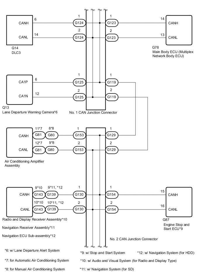
Disconnect the G124 No. 1 CAN junction connector.
-
Measure the resistance according to the value(s) in the table below.
Standard Resistance Tester Connection Condition Specified Condition G14-6 (CANH) - G14-4 (CG) Cable disconnected from negative (-) battery terminal 200 Ω or higher G14-14 (CANL) - G14-4 (CG) Cable disconnected from negative (-) battery terminal 200 Ω or higher Result Proceed to OK NG
NG 
REPAIR OR REPLACE CAN BRANCH WIRE CONNECTED TO DLC3 (CANH, CANL)
OK 
-
-
CONNECT CONNECTOR
-
Reconnect wire harness No. 1 CAN junction connector.
Result Proceed to NEXT
NEXT
-
-
CHECK FOR SHORT TO GND IN CAN BUS WIRE (NO. 3 CAN JUNCTION CONNECTOR SIDE)
-
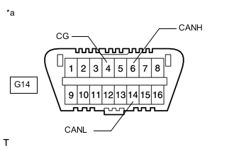
*a Front view of DLC3 Disconnect the N28 No. 3 CAN junction connector.
-
Measure the resistance according to the value(s) in the table below.
Standard Resistance Tester Connection Condition Specified Condition G14-6 (CANH) - G14-4 (CG) Cable disconnected from negative (-) battery terminal 200 Ω or higher G14-14 (CANL) - G14-4 (CG) Cable disconnected from negative (-) battery terminal 200 Ω or higher Result Proceed to OK NG
NG 
CONNECT CONNECTOR Click here
OK
-
-
CHECK FOR SHORT TO GND IN CAN BUS WIRE (NO. 3 CAN JUNCTION CONNECTOR)
-
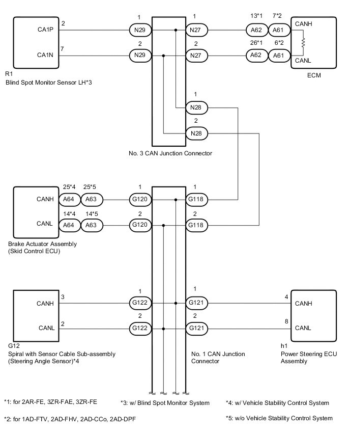
Disconnect the No. 3 CAN junction connectors.
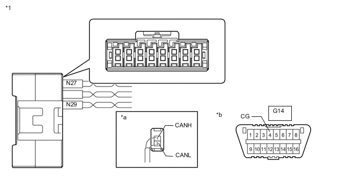
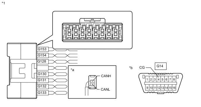
*1 No. 3 CAN Junction Connector - - *a Rear view of wire harness connector
(to No. 3 CAN Junction Connector)
*b Front view of DLC3 Code Color (CANH Side) Color (CANL Side) Connect to N27 Y W ECM N29 R W Blind Spot Monitor Sensor LH* *: w/ Blind Spot Monitor System
-
Measure the resistance according to the value(s) in the table below.
Standard Resistance *: w/ Blind Spot Monitor SystemTester Connection Condition Specified Condition N27-1 (CANH) - G14-4 (CG) Cable disconnected from negative (-) battery terminal 200 Ω or higher N27-2 (CANL) - G14-4 (CG) Cable disconnected from negative (-) battery terminal 200 Ω or higher N29-1 (CANH) - G14-4 (CG)* Cable disconnected from negative (-) battery terminal 200 Ω or higher N29-2 (CANL) - G14-4 (CG)* Cable disconnected from negative (-) battery terminal 200 Ω or higher
Result Result Proceed to OK A NG (to ECM CAN main wire) B NG (to blind spot monitor sensor LH CAN branch wire [w/ Blind Spot Monitor System]) C
A
REPLACE NO. 3 CAN JUNCTION CONNECTOR
C
CONNECT CONNECTOR Click here
B
-
-
CONNECT CONNECTOR
-
Reconnect all wire harness No. 3 CAN junction connectors.
Result Proceed to NEXT
NEXT
-
-
CHECK FOR SHORT TO GND IN CAN BUS WIRE (ECM)
-
Disconnect the ECM connector.
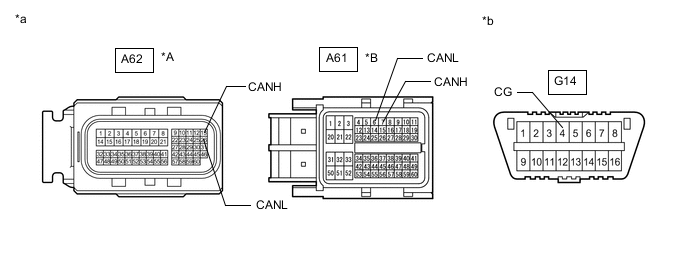
*A for 2AR-FE, 3ZR-FAE, 3ZR-FE *B for 1AD-FTV, 2AD-FHV, 2AD-CCo, 2AD-DPF *a Front view of wire harness connector
(to ECM)
*b Front view of DLC3 -
Measure the resistance according to the value(s) in the table below.
Standard Resistance for 2AR-FE, 3ZR-FAE, 3ZR-FE Tester Connection Condition Specified Condition A62-13 (CANH) - G14-4 (CG) Cable disconnected from negative (-) battery terminal 200 Ω or higher A62-26 (CANL) - G14-4 (CG) Cable disconnected from negative (-) battery terminal 200 Ω or higher for 1AD-FTV, 2AD-FHV, 2AD-CCo, 2AD-DPF Tester Connection Condition Specified Condition A61-7 (CANH) - G14-4 (CG) Cable disconnected from negative (-) battery terminal 200 Ω or higher A61-6 (CANL) - G14-4 (CG) Cable disconnected from negative (-) battery terminal 200 Ω or higher Result Proceed to OK NG
OK
REPLACE ECM for 2AR-FE: Click here
REPLACE ECM for 3ZR-FAE: Click here
REPLACE ECM for 3ZR-FE: Click here
REPLACE ECM for 1AD-FTV: Click here
REPLACE ECM for 2AD-FHV: Click here
REPLACE ECM for 2AD-CCo, 2AD-DPF: Click hereNG
REPAIR OR REPLACE CAN MAIN WIRE CONNECTED TO ECM (CANH, CANL)
-
-
CONNECT CONNECTOR
-
Reconnect all wire harness No. 3 CAN junction connectors.
Result Proceed to NEXT
NEXT
-
-
CHECK FOR SHORT TO GND IN CAN BUS WIRE (BLIND SPOT MONITOR SENSOR LH)
-
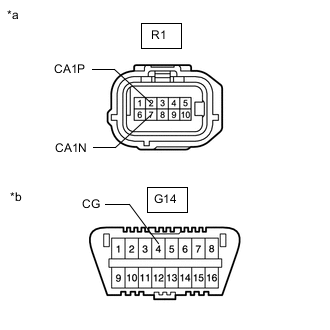
*a Front view of wire harness connector
(to Blind Spot Monitor Sensor LH)
*b Front view of DLC3 Disconnect the blind spot monitor sensor LH connector.
-
Measure the resistance according to the value(s) in the table below.
Standard Resistance Tester Connection Condition Specified Condition R1-2 (CA1P) - G14-4 (CG) Cable disconnected from negative (-) battery terminal 200 Ω or higher R1-7 (CA1N) - G14-4 (CG) Cable disconnected from negative (-) battery terminal 200 Ω or higher Result Proceed to OK NG
OK
REPLACE BLIND SPOT MONITOR SENSOR LH Click here
NG
REPAIR OR REPLACE CAN BRANCH WIRE CONNECTED TO BLIND SPOT MONITOR SENSOR LH (CA1P, CA1N)
-
-
CONNECT CONNECTOR
-
Reconnect wire harness No. 3 CAN junction connector.
Result Proceed to NEXT
NEXT
-
-
CHECK FOR SHORT TO GND IN CAN BUS WIRE (NO. 1 CAN JUNCTION CONNECTOR - NO. 3 CAN JUNCTION CONNECTOR)
-
Disconnect the No. 1 CAN junction connector.
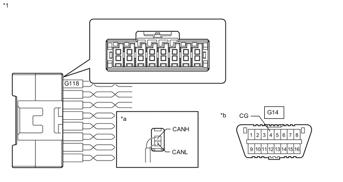
*1 No. 1 CAN Junction Connector - - *a Rear view of wire harness connector
(to No. 1 CAN Junction Connector)
*b Front view of DLC3 Code Color (CANH Side) Color (CANL Side) Connect to G118 L W No. 3 CAN Junction Connector -
Measure the resistance according to the value(s) in the table below.
Standard Resistance Tester Connection Condition Specified Condition G118-1 (CANH) - G14-4 (CG) Cable disconnected from negative (-) battery terminal 200 Ω or higher G118-2 (CANL) - G14-4 (CG) Cable disconnected from negative (-) battery terminal 200 Ω or higher Result Proceed to OK NG
NG
REPAIR OR REPLACE CAN MAIN WIRE OR CONNECTOR (NO. 1 CAN JUNCTION CONNECTOR - NO. 3 CAN JUNCTION CONNECTOR)
OK
-
-
CONNECT CONNECTOR
-
Reconnect wire harness No. 1 CAN junction connector.
Result Proceed to NEXT
NEXT
-
-
CHECK FOR SHORT TO GND IN CAN BUS WIRE (NO. 2 CAN JUNCTION CONNECTOR SIDE)
-

*a Front view of DLC3 Disconnect the G129 No. 2 CAN junction connector.
-
Measure the resistance according to the value(s) in the table below.
Standard Resistance Tester Connection Condition Specified Condition G14-6 (CANH) - G14-4 (CG) Cable disconnected from negative (-) battery terminal 200 Ω or higher G14-14 (CANL) - G14-4 (CG) Cable disconnected from negative (-) battery terminal 200 Ω or higher Result Proceed to OK NG
NG
CONNECT CONNECTOR Click here
OK
-
-
CHECK FOR SHORT TO GND IN CAN BUS WIRE (NO. 2 CAN JUNCTION CONNECTOR)
-
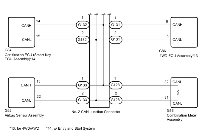
Disconnect the No. 2 CAN junction connectors.
*1 No. 2 CAN Junction Connector - - *a Rear view of wire harness connector
(to No. 2 CAN Junction Connector)
*b Front view of DLC3 Code Color (CANH Side) Color (CANL Side) Connect to G128 G W Combination Meter Assembly G130 Y W
-
Radio and Display Receiver Assembly*1
-
Navigation Receiver Assembly*2
-
Navigation ECU Sub-assembly*3
G131 L W 4WD ECU Assembly*4 G132 R W Certification ECU (Smart Key ECU Assembly)*5 G133 BR W Airbag Sensor Assembly G153 B W Air Conditioning Amplifier Assembly G154 LG W Engine Stop and Start ECU*6 *1: w/ Audio and Visual System (for Radio and Display Type)
*2: w/ Navigation System (for SD)
*3: w/ Navigation System (for HDD)
*4: for 4WD/AWD
*5: w/ Entry and Start System
*6: w/ Stop and Start System
-
-
Measure the resistance according to the value(s) in the table below.
Standard Resistance *1: w/ Audio and Visual System (for Radio and Display Type)Tester Connection Condition Specified Condition G128-1 (CANH) - G14-4 (CG) Cable disconnected from negative (-) battery terminal 200 Ω or higher G128-2 (CANL) - G14-4 (CG) Cable disconnected from negative (-) battery terminal 200 Ω or higher G130-1 (CANH) - G14-4 (CG)*1, *2, *3 Cable disconnected from negative (-) battery terminal 200 Ω or higher G130-2 (CANL) - G14-4 (CG)*1, *2, *3 Cable disconnected from negative (-) battery terminal 200 Ω or higher G131-1 (CANH) - G14-4 (CG)*4 Cable disconnected from negative (-) battery terminal 200 Ω or higher G131-2 (CANL) - G14-4 (CG)*4 Cable disconnected from negative (-) battery terminal 200 Ω or higher G132-1 (CANH) - G14-4 (CG)*5 Cable disconnected from negative (-) battery terminal 200 Ω or higher G132-2 (CANL) - G14-4 (CG)*5 Cable disconnected from negative (-) battery terminal 200 Ω or higher G133-1 (CANH) - G14-4 (CG) Cable disconnected from negative (-) battery terminal 200 Ω or higher G133-2 (CANL) - G14-4 (CG) Cable disconnected from negative (-) battery terminal 200 Ω or higher G153-1 (CANH) - G14-4 (CG) Cable disconnected from negative (-) battery terminal 200 Ω or higher G153-2 (CANL) - G14-4 (CG) Cable disconnected from negative (-) battery terminal 200 Ω or higher G154-1 (CANH) - G14-4 (CG)*6 Cable disconnected from negative (-) battery terminal 200 Ω or higher G154-2 (CANL) - G14-4 (CG)*6 Cable disconnected from negative (-) battery terminal 200 Ω or higher
*2: w/ Navigation System (for SD)
*3: w/ Navigation System (for HDD)
*4: for 4WD/AWD
*5: w/ Entry and Start System
*6: w/ Stop and Start System
Result Result Proceed to OK A NG (to air conditioning amplifier assembly CAN branch wire) B NG (to engine stop and start ECU CAN branch wire [w/ Stop and Start System]) C NG (to combination meter assembly CAN main wire) D NG (to radio and display receiver assembly [w/ Audio and Visual System {for Radio and Display Type}], navigation ECU receiver assembly [w/ Navigation System {for SD}] or navigation ECU sub-assembly [w/ Navigation System {for HDD}] CAN branch wire) E NG (to 4WD ECU assembly CAN branch wire [for 4WD/AWD]) F NG (to certification ECU [smart key ECU assembly] CAN branch wire [w/ Entry and Start System]) G NG (to airbag sensor assembly CAN branch wire) H
A
REPLACE NO. 2 CAN JUNCTION CONNECTOR
C
CONNECT CONNECTOR Click here
D
CONNECT CONNECTOR Click here
E
CONNECT CONNECTOR Click here
F
CONNECT CONNECTOR Click here
G
CONNECT CONNECTOR Click here
H
CONNECT CONNECTOR Click here
B
-
-
CONNECT CONNECTOR
-
Reconnect all wire harness No. 2 CAN junction connectors.
Result Proceed to NEXT
NEXT
-
-
CHECK FOR SHORT TO GND IN CAN BUS WIRE (AIR CONDITIONING AMPLIFIER ASSEMBLY)
-
Disconnect the air conditioning amplifier assembly connector.
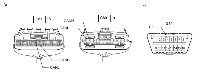
*A for Automatic Air Conditioning System *B for Manual Air Conditioning System *a Rear view of wire harness connector
(to Air Conditioning Amplifier Assembly)
*b Front view of DLC3 -
Measure the resistance according to the value(s) in the table below.
Standard Resistance for Automatic Air Conditioning System Tester Connection Condition Specified Condition G81-11 (CANH) - G14-4 (CG) Cable disconnected from negative (-) battery terminal 200 Ω or higher G81-12 (CANL) - G14-4 (CG) Cable disconnected from negative (-) battery terminal 200 Ω or higher for Manual Air Conditioning System Tester Connection Condition Specified Condition G80-8 (CANH) - G14-4 (CG) Cable disconnected from negative (-) battery terminal 200 Ω or higher G80-9 (CANL) - G14-4 (CG) Cable disconnected from negative (-) battery terminal 200 Ω or higher Result Proceed to OK NG
OK
REPLACE AIR CONDITIONING AMPLIFIER ASSEMBLY Click here
NG
REPAIR OR REPLACE CAN BRANCH WIRE CONNECTED TO AIR CONDITIONING AMPLIFIER ASSEMBLY (CANH, CANL)
-
-
CONNECT CONNECTOR
-
Reconnect all wire harness No. 2 CAN junction connectors.
Result Proceed to NEXT
NEXT
-
-
CHECK FOR SHORT TO GND IN CAN BUS WIRE (ENGINE STOP AND START ECU)
-
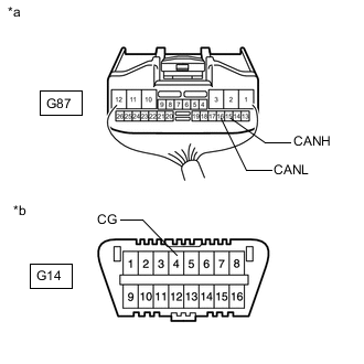
*a Rear view of wire harness connector
(to Engine Stop and Start ECU)
*b Front view of DLC3 Disconnect the engine stop and start ECU connector.
-
Measure the resistance according to the value(s) in the table below.
Standard Resistance Tester Connection Condition Specified Condition G87-15 (CANH) - G14-4 (CG) Cable disconnected from negative (-) battery terminal 200 Ω or higher G87-16 (CANH) - G14-4 (CG) Cable disconnected from negative (-) battery terminal 200 Ω or higher Result Proceed to OK NG
OK
REPLACE ENGINE STOP AND START ECU Click here
NG
REPAIR OR REPLACE CAN BRANCH WIRE CONNECTED TO ENGINE STOP AND START ECU (CANH, CANL)
-
-
CONNECT CONNECTOR
-
Reconnect all wire harness No. 2 CAN junction connectors.
Result Proceed to NEXT
NEXT
-
-
CHECK FOR SHORT TO GND IN CAN BUS WIRE (COMBINATION METER ASSEMBLY)
-
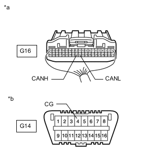
*a Rear view of wire harness connector
(to Combination Meter Assembly)
*b Front view of DLC3 Disconnect the combination meter assembly connector.
-
Measure the resistance according to the value(s) in the table below.
Standard Resistance Tester Connection Condition Specified Condition G16-32 (CANH) - G14-4 (CG) Cable disconnected from negative (-) battery terminal 200 Ω or higher G16-31 (CANL) - G14-4 (CG) Cable disconnected from negative (-) battery terminal 200 Ω or higher Result Proceed to OK NG
OK
REPLACE COMBINATION METER ASSEMBLY Click here
NG
REPAIR OR REPLACE CAN MAIN WIRE CONNECTED TO COMBINATION METER ASSEMBLY (CANH, CANL)
-
-
CONNECT CONNECTOR
-
Reconnect all wire harness No. 2 CAN junction connectors.
Result Proceed to NEXT
NEXT
-
-
CHECK VEHICLE TYPE
-
Check for vehicle types.
Result Proceed to w/ Audio and Visual System (for Radio and Display Type) w/ Navigation System (for SD) w/ Navigation System (for HDD)
w/ Navigation System (for SD)
CHECK FOR SHORT TO GND IN CAN BUS WIRE (NAVIGATION RECEIVER ASSEMBLY) Click here
w/ Navigation System (for HDD)
CHECK FOR SHORT TO GND IN CAN BUS WIRE (NAVIGATION ECU SUB-ASSEMBLY) Click here
w/ Audio and Visual System (for Radio and Display Type)
-
-
CHECK FOR SHORT TO GND IN CAN BUS WIRE (RADIO AND DISPLAY RECEIVER ASSEMBLY)
-
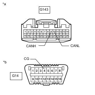
*a Front view of wire harness connector
(to Radio and Display Receiver Assembly)
*b Front view of DLC3 Disconnect the radio and display receiver assembly connector.
-
Measure the resistance according to the value(s) in the table below.
Standard Resistance Tester Connection Condition Specified Condition G143-9 (CANH) - G14-4 (CG) Cable disconnected from negative (-) battery terminal 200 Ω or higher G143-10 (CANL) - G14-4 (CG) Cable disconnected from negative (-) battery terminal 200 Ω or higher Result Proceed to OK NG
OK
REPLACE RADIO AND DISPLAY RECEIVER ASSEMBLY Click here
NG
REPAIR OR REPLACE CAN BRANCH WIRE CONNECTED TO RADIO AND DISPLAY RECEIVER ASSEMBLY (CANH, CANL)
-
-
CHECK FOR SHORT TO GND IN CAN BUS WIRE (NAVIGATION RECEIVER ASSEMBLY)
-
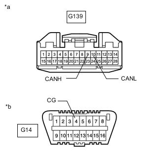
*a Front view of wire harness connector
(to Navigation Receiver Assembly)
*b Front view of DLC3 Disconnect the navigation receiver assembly connector.
-
Measure the resistance according to the value(s) in the table below.
Standard Resistance Tester Connection Condition Specified Condition G139-9 (CANH) - G14-4 (CG) Cable disconnected from negative (-) battery terminal 200 Ω or higher G48-10 (CANL) - G14-4 (CG) Cable disconnected from negative (-) battery terminal 200 Ω or higher Result Proceed to OK NG
OK
REPLACE NAVIGATION RECEIVER ASSEMBLY Click here
NG
REPAIR OR REPLACE CAN BRANCH WIRE CONNECTED TO NAVIGATION RECEIVER ASSEMBLY (CANH, CANL)
-
-
CHECK FOR SHORT TO GND IN CAN BUS WIRE (NAVIGATION ECU SUB-ASSEMBLY)
-
*a Front view of wire harness connector
(to Navigation ECU Sub-assembly)
*b Front view of DLC3 Disconnect the navigation ECU sub-assembly connector.
-
Measure the resistance according to the value(s) in the table below.
Standard Resistance Tester Connection Condition Specified Condition G139-9 (CANH) - G14-4 (CG) Cable disconnected from negative (-) battery terminal 200 Ω or higher G48-10 (CANL) - G14-4 (CG) Cable disconnected from negative (-) battery terminal 200 Ω or higher Result Proceed to OK NG
OK
REPLACE NAVIGATION ECU SUB-ASSEMBLY Click here
NG
REPAIR OR REPLACE CAN BRANCH WIRE CONNECTED TO NAVIGATION ECU SUB-ASSEMBLY (CANH, CANL)
-
-
CONNECT CONNECTOR
-
Reconnect all wire harness No. 2 CAN junction connectors.
Result Proceed to NEXT
NEXT
-
-
CHECK FOR SHORT TO GND IN CAN BUS WIRE (4WD ECU ASSEMBLY)
-
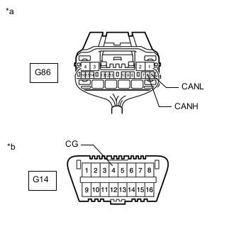
*a Rear view of wire harness connector
(to 4WD ECU Assembly)
*b Front view of DLC3 Disconnect the 4WD ECU assembly connector.
-
Measure the resistance according to the value(s) in the table below.
Standard Resistance Tester Connection Condition Specified Condition G86-6 (CANH) - G14-4 (CG) Cable disconnected from negative (-) battery terminal 200 Ω or higher G86-5 (CANL) - G14-4 (CG) Cable disconnected from negative (-) battery terminal 200 Ω or higher Result Proceed to OK NG
OK
REPLACE 4WD ECU ASSEMBLY Click here
NG
REPAIR OR REPLACE CAN BRANCH WIRE CONNECTED TO 4WD ECU ASSEMBLY (CANH, CANL)
-
-
CONNECT CONNECTOR
-
Reconnect all wire harness No. 2 CAN junction connectors.
Result Proceed to NEXT
NEXT
-
-
CHECK FOR SHORT TO GND IN CAN BUS WIRE (CERTIFICATION ECU)
-
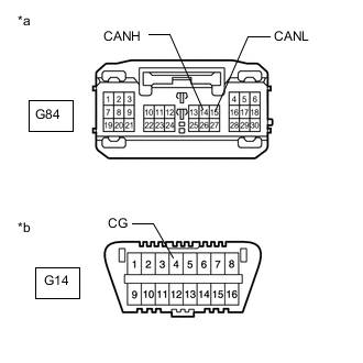
*a Front view of wire harness connector
(to Certification ECU [Smart Key ECU Assembly])
*b Front view of DLC3 Disconnect the certification ECU (smart key ECU assembly) connector.
-
Measure the resistance according to the value(s) in the table below.
Standard Resistance Tester Connection Condition Specified Condition G84-14 (CANH) - G14-4 (CG) Cable disconnected from negative (-) battery terminal 200 Ω or higher G84-15 (CANL) - G14-4 (CG) Cable disconnected from negative (-) battery terminal 200 Ω or higher Result Proceed to OK NG
OK
REPLACE CERTIFICATION ECU (SMART KEY ECU ASSEMBLY)
NG
REPAIR OR REPLACE CAN BRANCH WIRE CONNECTED TO CERTIFICATION ECU (CANH, CANL)
-
-
CONNECT CONNECTOR
-
Reconnect all wire harness No. 2 CAN junction connectors.
Result Proceed to NEXT
NEXT
-
-
CHECK FOR SHORT TO GND IN CAN BUS WIRE (AIRBAG SENSOR ASSEMBLY)
-
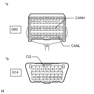
*a Rear view of wire harness connector
(to Airbag Sensor Assembly)
*b Front view of DLC3 Disconnect the airbag sensor assembly connector.
-
Measure the resistance according to the value(s) in the table below.
Standard Resistance Tester Connection Condition Specified Condition G92-13 (CANH) - G14-4 (CG) Cable disconnected from negative (-) battery terminal 200 Ω or higher G92-22 (CANL) - G14-4 (CG) Cable disconnected from negative (-) battery terminal 200 Ω or higher Result Proceed to OK NG
OK
REPLACE AIR BAG SENSOR ASSEMBLY Click here
NG
REPAIR OR REPLACE CAN BRANCH WIRE CONNECTED TO AIRBAG SENSOR ASSEMBLY (CANH, CANL)
-
-
CONNECT CONNECTOR
-
Reconnect wire harness No. 2 CAN junction connector.
Result Proceed to NEXT
NEXT
-
-
CHECK FOR SHORT TO GND IN CAN BUS WIRE (NO. 1 CAN JUNCTION CONNECTOR)
-
Disconnect the No. 1 CAN junction connectors.
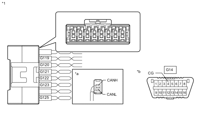
*1 No. 1 CAN Junction Connector - - *a Rear view of wire harness connector
(to No. 1 CAN Junction Connector)
*b Front view of DLC3 Code Color (CANH Side) Color (CANL Side) Connect to G119 V W No. 2 CAN Junction Connector G120 R W Brake Actuator Assembly (Skid Control ECU) G121 LG W Power Steering ECU Assembly G122 P W Spiral with Sensor Cable Sub-assembly (Steering Angle Sensor)*1 G123 Y W Main Body ECU (Multiplex Network Body ECU) G125 G W Lane Departure Warning Camera*2 *1: w/ Vehicle Stability Control System
*2: w/ Lane Departure Alert System
-
Measure the resistance according to the value(s) in the table below.
Standard Resistance *1: w/ Vehicle Stability Control SystemTester Connection Condition Specified Condition G119-1 (CANH) - G14-4 (CG) Cable disconnected from negative (-) battery terminal 200 Ω or higher G119-2 (CANL) - G14-4 (CG) Cable disconnected from negative (-) battery terminal 200 Ω or higher G120-1 (CANH) - G14-4 (CG) Cable disconnected from negative (-) battery terminal 200 Ω or higher G120-2 (CANL) - G14-4 (CG) Cable disconnected from negative (-) battery terminal 200 Ω or higher G121-1 (CANH) - G14-4 (CG) Cable disconnected from negative (-) battery terminal 200 Ω or higher G121-2 (CANL) - G14-4 (CG) Cable disconnected from negative (-) battery terminal 200 Ω or higher G122-1 (CANH) - G14-4 (CG)*1 Cable disconnected from negative (-) battery terminal 200 Ω or higher G122-2 (CANL) - G14-4 (CG)*1 Cable disconnected from negative (-) battery terminal 200 Ω or higher G123-1 (CANH) - G14-4 (CG) Cable disconnected from negative (-) battery terminal 200 Ω or higher G123-2 (CANL) - G14-4 (CG) Cable disconnected from negative (-) battery terminal 200 Ω or higher G125-1 (CANH) - G14-4 (CG)*2 Cable disconnected from negative (-) battery terminal 200 Ω or higher G125-2 (CANL) - G14-4 (CG)*2 Cable disconnected from negative (-) battery terminal 200 Ω or higher
*2: w/ Lane Departure Alert System
Result Result Proceed to OK A NG (to brake actuator assembly [skid control ECU] CAN branch wire) B NG (to power steering ECU assembly CAN branch wire) C NG (to spiral with sensor cable sub-assembly [steering angle sensor] CAN branch wire [w/ Vehicle Stability Control System]) D NG (to main body ECU [multiplex network body ECU] CAN branch wire) E NG (to lane departure warning camera CAN branch wire [w/ Lane Departure Alert System]) F NG (to No. 2 CAN junction connector CAN main wire) G
A
REPLACE NO. 1 CAN JUNCTION CONNECTOR
C
CONNECT CONNECTOR Click here
D
CONNECT CONNECTOR Click here
E
CONNECT CONNECTOR Click here
F
CONNECT CONNECTOR Click here
G
REPAIR OR REPLACE CAN MAIN WIRE OR CONNECTOR (NO. 1 CAN JUNCTION CONNECTOR - NO. 2 CAN JUNCTION CONNECTOR)
B
-
-
CONNECT CONNECTOR
-
Reconnect all wire harness No. 1 CAN junction connectors.
Result Proceed to NEXT
NEXT
-
-
CHECK FOR SHORT TO GND IN CAN BUS WIRE (SKID CONTROL ECU)
-
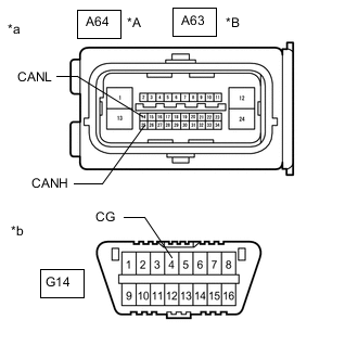
*A w/ Vehicle Stability Control System *B w/o Vehicle Stability Control System *a Front view of wire harness connector
(to Brake Actuator Assembly [Skid Control ECU])
*b Front view of DLC3 Disconnect the brake actuator assembly (skid control ECU) connector.
-
Measure the resistance according to the value(s) in the table below.
Standard Resistance w/ Vehicle Stability Control System Tester Connection Condition Specified Condition A64-25 (CANH) - G14-4 (CG) Cable disconnected from negative (-) battery terminal 200 Ω or higher A64-14 (CANL) - G14-4 (CG) Cable disconnected from negative (-) battery terminal 200 Ω or higher w/o Vehicle Stability Control System Tester Connection Condition Specified Condition A63-25 (CANH) - G14-4 (CG) Cable disconnected from negative (-) battery terminal 200 Ω or higher A63-14 (CANL) - G14-4 (CG) Cable disconnected from negative (-) battery terminal 200 Ω or higher Result Proceed to OK NG
OK
REPLACE BRAKE ACTUATOR ASSEMBLY (SKID CONTROL ECU) w/ Vehicle Stability Control System: Click here
REPLACE BRAKE ACTUATOR ASSEMBLY (SKID CONTROL ECU) w/o Vehicle Stability Control System: Click hereNG
REPAIR OR REPLACE CAN BRANCH WIRE CONNECTED TO SKID CONTROL ECU (CANH, CANL)
-
-
CONNECT CONNECTOR
-
Reconnect all wire harness No. 1 CAN junction connectors.
Result Proceed to NEXT
NEXT
-
-
CHECK FOR SHORT TO GND IN CAN BUS WIRE (POWER STEERING ECU ASSEMBLY)
-
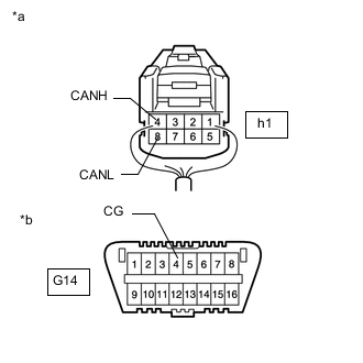
*a Rear view of wire harness connector
(to Power Steering ECU Assembly)
*b Front view of DLC3 Disconnect the power steering ECU assembly connector.
-
Measure the resistance according to the value(s) in the table below.
Standard Resistance Tester Connection Condition Specified Condition h1-4 (CANH) - G14-4 (CG) Cable disconnected from negative (-) battery terminal 200 Ω or higher h1-8 (CANL) - G14-4 (CG) Cable disconnected from negative (-) battery terminal 200 Ω or higher Result Proceed to OK NG
OK
REPLACE POWER STEERING ECU ASSEMBLY Click here
NG
REPAIR OR REPLACE CAN BRANCH WIRE CONNECTED TO POWER STEERING ECU ASSEMBLY (CANH, CANL)
-
-
CONNECT CONNECTOR
-
Reconnect all wire harness No. 1 CAN junction connectors.
Result Proceed to NEXT
NEXT
-
-
CHECK FOR SHORT TO GND IN CAN BUS WIRE (STEERING ANGLE SENSOR)
-
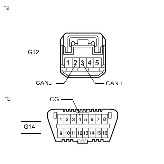
*a Front view of wire harness connector
(to Spiral with Sensor Cable Sub-assembly [Steering Angle Sensor])
*b Front view of DLC3 Disconnect the spiral with sensor cable sub-assembly (steering angle sensor) connector.
-
Measure the resistance according to the value(s) in the table below.
Standard Resistance Tester Connection Condition Specified Condition G12-3 (CANH) - G14-4 (CG) Cable disconnected from negative (-) battery terminal 200 Ω or higher G12-2 (CANL) - G14-4 (CG) Cable disconnected from negative (-) battery terminal 200 Ω or higher Result Proceed to OK NG
OK
REPLACE SPIRAL WITH SENSOR CABLE SUB-ASSEMBLY (STEERING ANGLE SENSOR) Click here
NG
REPAIR OR REPLACE CAN BRANCH WIRE CONNECTED TO STEERING ANGLE SENSOR (CANH, CANL)
-
-
CONNECT CONNECTOR
-
Reconnect all wire harness No. 1 CAN junction connectors.
Result Proceed to NEXT
NEXT
-
-
CHECK FOR SHORT TO GND IN CAN BUS WIRE (MAIN BODY ECU)
-
*a Rear view of wire harness connector
(to Main Body ECU [Multiplex Network Body ECU])
*b Front view of DLC3 Disconnect the main body ECU (multiplex network body ECU) connector.
-
Measure the resistance according to the value(s) in the table below.
Standard Resistance Tester Connection Condition Specified Condition G78-14 (CANH) - G14-4 (CG) Cable disconnected from negative (-) battery terminal 200 Ω or higher G78-13 (CANL) - G14-4 (CG) Cable disconnected from negative (-) battery terminal 200 Ω or higher Result Proceed to OK NG
OK
REPLACE MAIN BODY ECU (MULTIPLEX NETWORK BODY ECU) Click here
NG
REPAIR OR REPLACE CAN BRANCH WIRE CONNECTED TO MAIN BODY ECU (CANH, CANL)
-
-
CONNECT CONNECTOR
-
Reconnect all wire harness No. 1 CAN junction connectors.
Result Proceed to NEXT
NEXT
-
-
CHECK FOR SHORT TO GND IN CAN BUS WIRE (LANE DEPARTURE WARNING CAMERA)
-
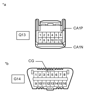
*a Front view of wire harness connector
(to Lane Departure Warning Camera)
*b Front view of DLC3 Disconnect the lane departure warning camera connector.
-
Measure the resistance according to the value(s) in the table below.
Standard Resistance Tester Connection Condition Specified Condition Q13-6 (CA1P) - G14-4 (CG) Cable disconnected from negative (-) battery terminal 200 Ω or higher Q13-12 (CA1N) - G14-4 (CG) Cable disconnected from negative (-) battery terminal 200 Ω or higher Result Proceed to OK NG
OK
REPLACE LANE DEPARTURE WARNING CAMERA Click here
NG
REPAIR OR REPLACE CAN BRANCH WIRE CONNECTED TO LANE DEPARTURE WARNING CAMERA (CA1P, CA1N)
-