CRUISE CONTROL SYSTEM Clutch Switch Circuit
DESCRIPTION
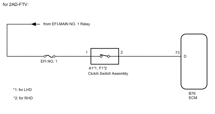
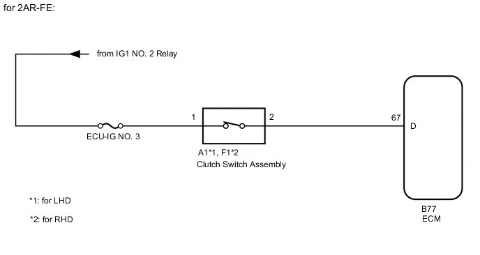
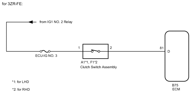
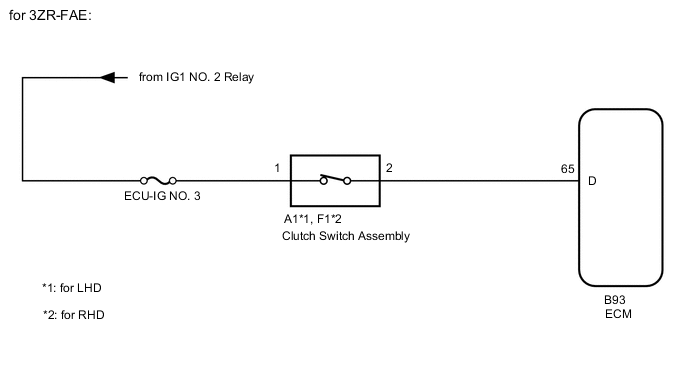
While depressing the clutch pedal, the clutch switch sends a signal to terminal D of the ECM. The ECM cancels cruise control when terminal D receives the signal.
WIRING DIAGRAM
CAUTION / NOTICE / HINT
Note
Inspect the fuses for circuits related to this system before performing the following inspection procedure.
PROCEDURE
-
INSPECT CLUTCH SWITCH ASSEMBLY
-
Remove the clutch switch assembly.
-
Inspect the clutch switch assembly.
Result Proceed to OK NG
NG 
REPLACE CLUTCH SWITCH ASSEMBLY Click here
OK 
-
-
CHECK HARNESS AND CONNECTOR (CLUTCH SWITCH ASSEMBLY - ECM AND BATTERY)
-
for 2AD-FTV
-
Disconnect the A1*1 or F1*2 clutch switch assembly connector.
-
*1: for LHD
*2: for RHD
-
-
Disconnect the B76 ECM connector.
-
Measure the resistance according to the value(s) in the table below.
Standard Resistance for LHD Tester Connection Condition Specified Condition A1-2 - B76-73 (D) Always Below 1 Ω A1-2 or B76-73 (D) - Body ground Always 10 kΩ or higher for RHD Tester Connection Condition Specified Condition F1-2 - B76-73 (D) Always Below 1 Ω F1-2 or B76-73 (D) - Body ground Always 10 kΩ or higher -
Measure the voltage according to the value(s) in the table below.
Standard Voltage for LHD Tester Connection Switch Condition Specified Condition A1-1 - Body ground Ignition switch ON 11 to 14 V A1-1 - Body ground Ignition switch off Below 1 V for RHD Tester Connection Switch Condition Specified Condition F1-1 - Body ground Ignition switch ON 11 to 14 V F1-1 - Body ground Ignition switch off Below 1 V
-
-
for 2AR-FE
-
Disconnect the A1*1 or F1*2 clutch switch assembly connector.
-
*1: for LHD
*2: for RHD
-
-
Disconnect the B77 ECM connector.
-
Measure the resistance according to the value(s) in the table below.
Standard Resistance for LHD Tester Connection Condition Specified Condition A1-2 - B77-67 (D) Always Below 1 Ω A1-2 or B77-67 (D) - Body ground Always 10 kΩ or higher for RHD Tester Connection Condition Specified Condition F1-2 - B77-67 (D) Always Below 1 Ω F1-2 or B77-67 (D) - Body ground Always 10 kΩ or higher -
Measure the voltage according to the value(s) in the table below.
Standard Voltage for LHD Tester Connection Switch Condition Specified Condition A1-1 - Body ground Ignition switch ON 11 to 14 V A1-1 - Body ground Ignition switch off Below 1 V for RHD Tester Connection Switch Condition Specified Condition F1-1 - Body ground Ignition switch ON 11 to 14 V F1-1 - Body ground Ignition switch off Below 1 V
-
-
for 3ZR-FE
-
Disconnect the A1*1 or F1*2 clutch switch assembly connector.
-
*1: for LHD
*2: for RHD
-
-
Disconnect the B75 ECM connector.
-
Measure the resistance according to the value(s) in the table below.
Standard Resistance for LHD Tester Connection Condition Specified Condition A1-2 - B75-81 (D) Always Below 1 Ω A1-2 or B75-81 (D) - Body ground Always 10 kΩ or higher for RHD Tester Connection Condition Specified Condition F1-2 - B75-81 (D) Always Below 1 Ω F1-2 or B75-81 (D) - Body ground Always 10 kΩ or higher -
Measure the voltage according to the value(s) in the table below.
Standard Voltage for LHD Tester Connection Switch Condition Specified Condition A1-1 - Body ground Ignition switch ON 11 to 14 V A1-1 - Body ground Ignition switch off Below 1 V for RHD Tester Connection Switch Condition Specified Condition F1-1 - Body ground Ignition switch ON 11 to 14 V F1-1 - Body ground Ignition switch off Below 1 V
-
-
for 3ZR-FAE
-
Disconnect the A1*1 or F1*2 clutch switch assembly connector.
-
*1: for LHD
*2: for RHD
-
-
Disconnect the B93 ECM connector.
-
Measure the resistance according to the value(s) in the table below.
Standard Resistance for LHD Tester Connection Condition Specified Condition A1-2 - B93-65 (D) Always Below 1 Ω A1-2 or B93-65 (D) - Body ground Always 10 kΩ or higher for RHD Tester Connection Condition Specified Condition F1-2 - B93-65 (D) Always Below 1 Ω F1-2 or B93-65 (D) - Body ground Always 10 kΩ or higher -
Measure the voltage according to the value(s) in the table below.
Standard Voltage for LHD Tester Connection Switch Condition Specified Condition A1-1 - Body ground Ignition switch ON 11 to 14 V A1-1 - Body ground Ignition switch off Below 1 V for RHD Tester Connection Switch Condition Specified Condition F1-1 - Body ground Ignition switch ON 11 to 14 V F1-1 - Body ground Ignition switch off Below 1 V
-
-
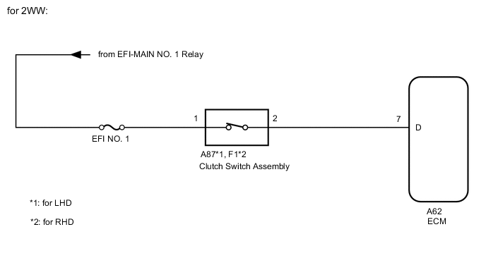
for 2WW
-
Disconnect the A87*1 or F1*2 clutch switch assembly connector.
-
*1: for LHD
*2: for RHD
-
-
Disconnect the A62 ECM connector.
-
Measure the resistance according to the value(s) in the table below.
Standard Resistance for LHD Tester Connection Condition Specified Condition A87-2 - A62-7 (D) Always Below 1 Ω A87-2 or A62-7 (D) - Body ground Always 10 kΩ or higher for RHD Tester Connection Condition Specified Condition F1-2 - A62-7 (D) Always Below 1 Ω F1-2 or A62-7 (D) - Body ground Always 10 kΩ or higher -
Measure the voltage according to the value(s) in the table below.
Standard Voltage for LHD Tester Connection Switch Condition Specified Condition A87-1 - Body ground Ignition switch ON 11 to 14 V A87-1 - Body ground Ignition switch off Below 1 V for RHD Tester Connection Switch Condition Specified Condition F1-1 - Body ground Ignition switch ON 11 to 14 V F1-1 - Body ground Ignition switch off Below 1 V
Result Proceed to OK NG -
OK
REPLACE ECM for 2AD-FTV: Click here
REPLACE ECM for 2AR-FE: Click here
REPLACE ECM for 3ZR-FAE: Click here
REPLACE ECM for 3ZR-FE: Click here
REPLACE ECM for 2WW: Click hereNG
REPAIR OR REPLACE HARNESS OR CONNECTOR
-