CRUISE CONTROL SYSTEM Cruise Control Switch Circuit
DESCRIPTION
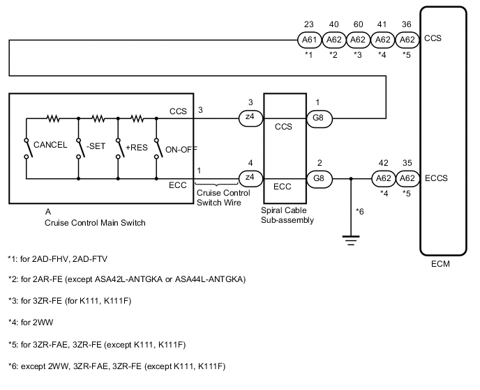
This circuit sends a signal to the ECM depending on the cruise control main switch condition. The battery supplies positive (+) battery voltage to the circuit control main switch. Then terminal CCS of the ECM receives the voltage according to the switch condition.
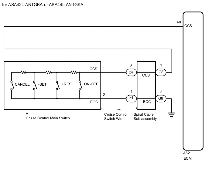
WIRING DIAGRAM
PROCEDURE
-
READ VALUE USING GTS
-
Check the Data List for proper functioning of the cruise control switch.
-
for 2AD-FTV, 2AD-FHV:
Powertrain > Cruise Control > Data ListTester Display Measurement Item Range Normal Condition Diagnostic Note CCS Main SW M-CPU Cruise control switch signal (Main CPU) ON or OFF ON: Cruise control switch on
OFF: Cruise control switch off
- Cancel Switch CANCEL switch signal ON or OFF ON: CANCEL switch on
OFF: CANCEL switch off
- SET/COAST Switch -SET switch signal ON or OFF ON: -SET switch on
OFF: -SET switch off
- RES/ACC Switch +RES switch signal ON or OFF ON: +RES switch on
OFF: +RES switch off
-
Powertrain > Cruise Control > Data ListTester Display CCS Main SW M-CPU Cancel Switch SET/COAST Switch RES/ACC Switch OK When the cruise control switch is operated, the display changes as shown above. -
for 2AR-FE, 3ZR-FE, 3ZR-FAE:
Powertrain > Cruise Control > Data ListTester Display Measurement Item Range Normal Condition Diagnostic Note Cancel Switch CANCEL switch status ON or OFF ON: CANCEL switch on
OFF: CANCEL switch off
- -SET Switch -SET switch status ON or OFF ON: -SET switch on
OFF: -SET switch off
- +RES Switch +RES switch status ON or OFF ON: +RES switch on
OFF: +RES switch off
- Cruise Ready Main-CPU Cruise control system standby condition ON or OFF Each time cruise control switch is pushed, ON or OFF changes - Cruise Ready Sub-CPU Cruise control system standby condition ON or OFF Each time cruise control switch is pushed, ON or OFF changes -
Powertrain > Cruise Control > Data ListTester Display Cancel Switch -SET Switch +RES Switch Cruise Ready Main-CPU Cruise Ready Sub-CPU OK When the cruise control switch is operated, the display changes as shown above. -
for 2WW:
Powertrain > Cruise Control > Data ListTester Display Measurement Item Range Normal Condition Diagnostic Note CANCEL SW CANCEL switch signal ON or OFF ON: CANCEL switch on
OFF: CANCEL switch off
- -SET SW -SET switch signal ON or OFF ON: -SET switch on
OFF: -SET switch off
- +RES SW +RES switch signal ON or OFF ON: +RES switch on
OFF: +RES switch off
- Cruise Control Switch Cruise control switch signal ON or OFF ON: Cruise control switch (ON/OFF) pushed
OFF: Cruise control switch (ON/OFF) released
-
Powertrain > Cruise Control > Data ListTester Display CANCEL SW -SET SW +RES SW Cruise Control Switch OK When the cruise control switch is operated, the display changes as shown above.
Result Proceed to OK NG -
OK 
PROCEED TO NEXT SUSPECTED AREA SHOWN IN PROBLEM SYMPTOMS TABLE Click here
NG 
-
-
INSPECT CRUISE CONTROL MAIN SWITCH
-
Remove the cruise control main switch.
-
Inspect the cruise control main switch.
Result Proceed to OK NG
NG
REPLACE CRUISE CONTROL MAIN SWITCH Click here
OK
-
-
CHECK CRUISE CONTROL SWITCH WIRE
-
Disconnect the z4 spiral cable sub-assembly connector.
-
Disconnect the A cruise control switch wire connector.
-
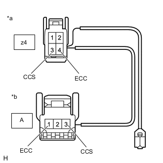
*a Front view of wire harness connector
(to Spiral Cable Sub-assembly)
*b Front view of wire harness connector
(to Cruise Control Switch)
except ASA42L-ANTGKA or ASA44L-ANTGKA:
Measure the resistance according to the value(s) in the table below.
Standard Resistance Tester Connection Condition Specified Condition z4-3 (CCS) - A-3 (CCS) Always Below 1 Ω z4-4 (ECC) - A-1 (ECC) Always Below 1 Ω z4-3 (CCS) or A-3 (CCS) - Body ground Always 10 kΩ or higher z4-4 (ECC) or A-1 (ECC) - Body ground Always 10 kΩ or higher -
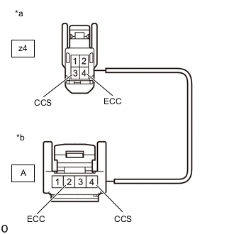
*a Front view of wire harness connector
(to Spiral Cable Sub-assembly)
*b Front view of wire harness connector
(to Cruise Control Main Switch)
for ASA42L-ANTGKA or ASA44L-ANTGKA:
Measure the resistance according to the value(s) in the table below.
Standard Resistance Tester Connection Condition Specified Condition z4-3 (CCS) - A-4 (CCS) Always Below 1 Ω z4-4 (ECC) - A-2 (ECC) Always Below 1 Ω z4-3 (CCS) or A-4 (CCS) - Body ground Always 10 kΩ or higher z4-4 (ECC) or A-2 (ECC) - Body ground Always 10 kΩ or higher Result Proceed to OK NG
NG
REPLACE CRUISE CONTROL SWITCH WIRE
OK
-
-
INSPECT SPIRAL CABLE SUB-ASSEMBLY
-
Remove the spiral cable sub-assembly.
for Single Type: Click here
for Dual Type: Click here
-
Inspect the spiral cable sub-assembly.
for Single Type: Click here
for Dual Type: Click here
Result Proceed to OK NG
NG
REPLACE SPIRAL CABLE SUB-ASSEMBLY for Single Type: Click here
REPLACE SPIRAL CABLE SUB-ASSEMBLY for Dual Type: Click hereOK
-
-
CHECK HARNESS AND CONNECTOR (SPIRAL CABLE SUB-ASSEMBLY - ECM AND BODY GROUND)
-
for 2AD-FHV, 2AD-FTV:
-
Disconnect the G8 spiral cable sub-assembly connector.
-
Disconnect the A61 ECM connector.
-
Measure the resistance according to the value(s) in the table below.
Standard Resistance Tester Connection Condition Specified Condition G8-1 (CCS) - A61-23 (CCS) Always Below 1 Ω G8-2 (ECC) - Body ground Always Below 1 Ω G8-1 (CCS) or A61-23 (CCS) - Body ground Always 10 kΩ or higher
-
-
for 2AR-FE:
-
Disconnect the G8 spiral cable sub-assembly connector.
-
Disconnect the A62 ECM connector.
-
Measure the resistance according to the value(s) in the table below.
Standard Resistance Tester Connection Condition Specified Condition G8-1 (CCS) - A62-40 (CCS) Always Below 1 Ω G8-2 (ECC) - Body ground Always Below 1 Ω G8-1 (CCS) or A62-40 (CCS) - Body ground Always 10 kΩ or higher
-
-
for 3ZR-FE (for K111, K111F):
-
Disconnect the G8 spiral cable sub-assembly connector.
-
Disconnect the A62 ECM connector.
-
Measure the resistance according to the value(s) in the table below.
Standard Resistance Tester Connection Condition Specified Condition G8-1 (CCS) - A62-60 (CCS) Always Below 1 Ω G8-2 (ECC) - Body ground Always Below 1 Ω G8-1 (CCS) or A62-60 (CCS) - Body ground Always 10 kΩ or higher
-
-
for 3ZR-FAE, 3ZR-FE (except K111, K111F):
-
Disconnect the G8 spiral cable sub-assembly connector.
-
Disconnect the A62 ECM connector.
-
Measure the resistance according to the value(s) in the table below.
Standard Resistance Tester Connection Condition Specified Condition G8-1 (CCS) - A62-36 (CCS) Always Below 1 Ω G8-2 (ECC) - A62-35 (ECCS) Always Below 1 Ω G8-1 (CCS) or A62-36 (CCS) - Body ground Always 10 kΩ or higher
-
-
for 2WW:
-
Disconnect the G8 spiral cable sub-assembly connector.
-
Disconnect the A62 ECM connector.
-
Measure the resistance according to the value(s) in the table below.
Standard Resistance Tester Connection Condition Specified Condition G8-1 (CCS) - A62-41 (CCS) Always Below 1 Ω G8-2 (ECC) - A62-42 (ECCS) Always Below 1 Ω G8-1 (CCS) or A62-41 (CCS) - Body ground Always 10 kΩ or higher
Result Proceed to OK NG -
OK
REPLACE ECM for 2AD-FHV: Click here
REPLACE ECM for 2AD-FTV: Click here
REPLACE ECM for 2AR-FE: Click here
REPLACE ECM for 3ZR-FAE: Click here
REPLACE ECM for 3ZR-FE: Click here
REPLACE ECM for 2WW: Click hereNG
REPAIR OR REPLACE HARNESS OR CONNECTOR
-