CLUTCH SYSTEM(for EC65A) BLEEDING

CAUTION / NOTICE / HINT
Note
Wash off clutch fluid immediately if it comes in contact with any painted surface.
Tech Tips
-
If any work is performed on the clutch system or if air in the clutch lines is suspected, bleed the air from the clutch hydraulic system.
-
In case of clutch fluid replacement, make sure that the old fluid is replaced in the clutch line between the reservoir and bleeder before bleeding.
PROCEDURE
-
REMOVE NO. 1 ENGINE COVER (w/ No. 1 Engine Cover)
-
REMOVE AIR CLEANER CAP SUB-ASSEMBLY
-
REMOVE AIR CLEANER CASE SUB-ASSEMBLY
-
REMOVE BATTERY
-
FILL BRAKE FLUID RESERVOIR
-
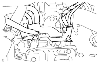
Separate the wire harness clamps from the battery carrier.
-
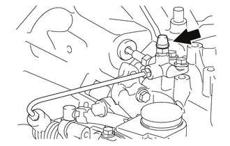
Remove the clutch master cylinder reservoir filler cap.
-
Fill the reservoir with brake fluid.
Brake Fluid SAE J1704 or FMVSS No. 116 DOT 4 Note
Make sure that there is sufficient brake fluid in the reservoir.
-
-
INSTALL BATTERY
-
BLEED CLUTCH LINE
-
When using the GTS:
-
Connect the GTS to the DLC3 with the ignition switch off.
-
Turn the ignition switch to ON.
Note
Check that electrical systems such as the air conditioning system, audio system and lighting system are off.
-
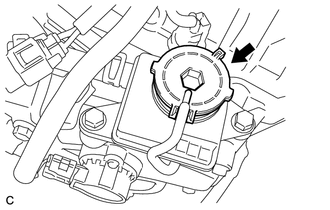
Remove the bleeder plug cap.
-
Connect a vinyl tube to the release cylinder bleeder plug.
-
Loosen the release cylinder bleeder plug.
-
Enter the following menus: Powertrain / Multi-Mode M/T / Air Bleeding.
Powertrain > Multi-Mode M/T > UtilityTester Display Air Bleeding Tech Tips
Bleed the air by following the steps displayed on the GTS.
-
When "Air Bleeding is complete" is displayed on the GTS, tighten the release cylinder bleeder plug to the specified torque.
- Torque:
- 8.4 N*m { 86 kgf*cm, 74 in.*lbf }
-
Install the bleeder plug cap.
-
Enter the following menus: Powertrain / Multi-Mode M/T / Active Test / Target Clutch Control.
Powertrain > Multi-Mode M/T > Active TestTester Display Target Clutch Control -
Select "Clamp position", and then "Standby position". Repeat this step 10 or more times.
-
Turn the GTS off.
-
Disconnect the GTS from the DLC3.
-
Turn the ignition switch off.
-
-
When not using the GTS:
-
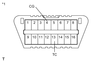
*1 DLC3 Using SST, connect terminals 13 (TC) and 4 (CG) of the DLC3 with the ignition switch off.
- SST
- 09843-18040
-
Turn the ignition switch to ON.
Note
-
Be sure to connect the terminals correctly. Failure to do so can damage the engine.
-
Check that electrical systems such as the air conditioning system, audio system and lighting system are off.
Tech Tips
The indicator lights on the combination meter blink to indicate the DTC output when terminals TC and CG are shorted.
-
-
Depress the brake pedal 7 or more times within 3 seconds.
-
Confirm that the buzzer beeps twice and depress the brake pedal.
-
With the brake pedal depressed, move the shift lever to M.
-
Release the brake pedal.
-
Move the shift lever to "+", M, "+", M, "+", M, "-", then N, and depress the brake pedal.
-
Confirm that the buzzer beeps 6 times and depress the brake pedal 3 or more times within 2 seconds.
-
Confirm that the buzzer beeps twice.
-
Remove the bleeder plug cap.
-
Connect a vinyl tube to the release cylinder bleeder plug.
-
Loosen the release cylinder bleeder plug.
-
Move the shift lever to "-", then back to M, and wait for 10 seconds or more.
-
Move the shift lever to "+", then back to M, and wait for 0.5 seconds or more.
-
If fluid free of air bubbles comes out of the release cylinder bleeder plug, tighten the release cylinder bleeder plug.
- Torque:
- 8.4 N*m { 86 kgf*cm, 74 in.*lbf }
If no fluid comes out, or air bubbles are present in the fluid that comes out of the release cylinder bleeder plug, perform the following steps until fluid free of air bubbles comes out of the release cylinder bleeder plug.
-
Move the shift lever to "-", then back to M, and wait for 0.5 seconds or more. Then, move the shift lever to "+", back to M, and wait for 0.5 seconds.
-
Tighten the release cylinder bleeder plug.*1
- Torque:
- 8.4 N*m { 86 kgf*cm, 74 in.*lbf }
-
Move the shift lever to "-", then back to M, and wait for 0.5 seconds or more.*2
-
Move the shift lever to "+", then back to M, and wait for 0.5 seconds or more.*3
-
Loosen the release cylinder bleeder plug.*4
-
If fluid free of air bubbles comes out of the release cylinder bleeder plug after performing steps *1 through *4 15 times, tighten the release cylinder bleeder plug.
- Torque:
- 8.4 N*m { 86 kgf*cm, 74 in.*lbf }
If air bubbles are present in the fluid that comes out of the release cylinder bleeder plug, perform steps *1 through *4 until fluid free of air bubbles comes out of the release cylinder bleeder plug.
-
Install the bleeder plug cap.
-
Move the shift lever to "-", then back to M, and wait for 0.5 seconds or more.
-
Move the shift lever to "-", then back to M, and wait for 0.5 seconds or more. Then, move the shift lever to "+", back to M, and wait for 0.5 seconds. Repeat this step at least 10 times.
-
Move the shift lever to N.
-
Turn the ignition switch off.
-
Wait for 20 seconds or more.
-
*1 DLC3 Remove SST from terminals 13 (TC) and 4 (CG).
- SST
- 09843-18040
-
-
-
INSPECT FOR FLUID LEAK
-
If fluid leaks are found, tighten or replace the leaking part.
-
-
REMOVE BATTERY
-
INSPECT FLUID LEVEL
-
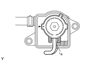
*a Full Level Inspect the fluid level and add fluid if necessary.
Brake Fluid SAE J1704 or FMVSS No. 116 DOT 4 If fluid leaks are found, tighten or replace the leaking part.
-
Install the clutch master cylinder reservoir filler cap.
Note
-
Tighten the clutch master cylinder reservoir filler cap until the rims of the clutch master cylinder reservoir filler cap and clutch master cylinder reservoir sub-assembly fit firmly.
-
Confirm that the O-ring is not cut.
-
Confirm that the clutch master cylinder reservoir filler cap is free of foreign matter.
-
-
Connect the 2 wire harness clamps.
-
-
INSTALL BATTERY
-
INSTALL AIR CLEANER CASE SUB-ASSEMBLY
-
INSTALL AIR CLEANER CAP SUB-ASSEMBLY
-
INSTALL NO. 1 ENGINE COVER (w/ No. 1 Engine Cover)
-
PERFORM INITIALIZATION OF MULTI-MODE MANUAL TRANSMISSION SYSTEM
-
PERFORM LEARNING OF MULTI-MODE MANUAL TRANSMISSION SYSTEM