CAN COMMUNICATION SYSTEM(w/o Central Gateway ECU) Open in CAN Main Bus Line (LHD Models)
DESCRIPTION
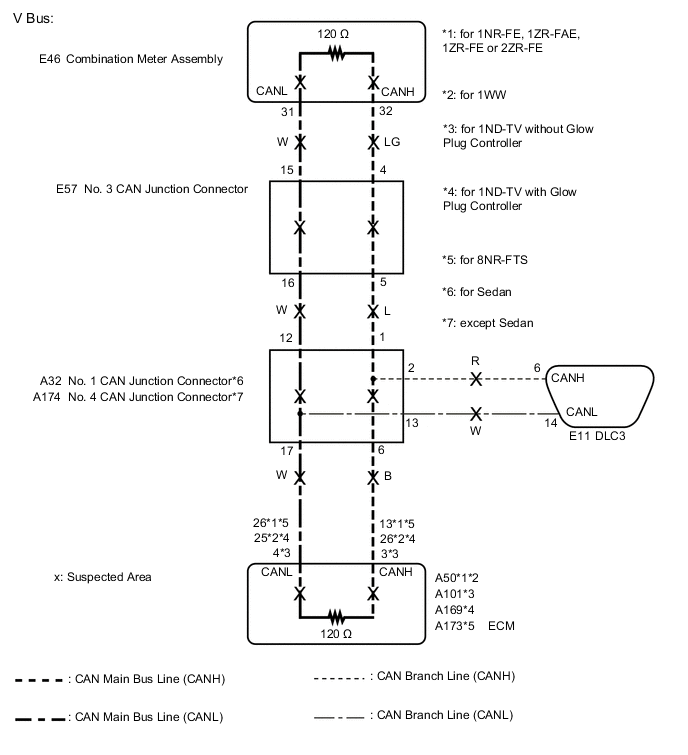
There may be an open circuit in one of the V bus main lines and/or a DLC3 branch line when the resistance between terminals 6 (CANH) and 14 (CANL) of the DLC3 is 70 Ω or higher.
| Symptom | Trouble Area |
|---|---|
| Resistance between terminals 6 (CANH) and 14 (CANL) of the DLC3 is 70 Ω or higher. |
|
-
*1: for Sedan
-
*2: except Sedan
This malfunction is not related to the lines of a CAN main bus branch or to ECUs or sensors connected to a CAN main bus branch.
WIRING DIAGRAM
CAUTION / NOTICE / HINT
Note
-
Before measuring the resistance of the CAN bus, turn the ignition switch off and leave the vehicle for 1 minute or more without operating the key or any switches, or opening or closing the doors. After that, disconnect the cable from the negative (-) battery terminal and leave the vehicle for 1 minute or more before measuring the resistance.
-
After turning the ignition switch off, waiting time may be required before disconnecting the cable from the negative (-) battery terminal. Therefore, make sure to read the disconnecting the cable from the negative (-) battery terminal notices before proceeding with work.
-
Because the order of diagnosis is important to allow correct diagnosis, make sure to begin troubleshooting using How to Proceed with Troubleshooting when CAN communication system related DTCs are output.
-
After performing repairs, perform the DTC check procedure and confirm that the DTCs are not output again.
-
DTC check procedure: Turn the ignition switch to ON and wait at least 31 seconds, and then drive the vehicle at a speed of 20 km/h (12 mph) or more.
-
After the repair, perform the CAN bus check and check that all the ECUs and sensors connected to the CAN communication system are displayed.
Tech Tips
-
Operating the ignition switch, any other switches or a door triggers related ECU and sensor communication on the CAN. This communication will cause the resistance value to change.
-
Even after DTCs are cleared, if a DTC is stored again after driving the vehicle for a while, the malfunction may be occurring due to vibration of the vehicle. In such a case, wiggling the ECUs or wire harness while performing the inspection below may help determine the cause of the malfunction.
PROCEDURE
-
CHECK FOR OPEN IN CAN BUS LINES (DLC3 BRANCH LINE)
-
Disconnect the cable from the negative (-) battery terminal.
-
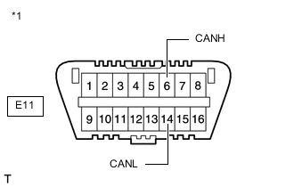
*1 DLC3 Measure the resistance according to the value(s) in the table below.
Standard Resistance Tester Connection Condition Specified Condition E11-6 (CANH) - E11-14 (CANL) Cable disconnected from negative (-) battery terminal 108 to 132 Ω Note
When the measured value is 133 Ω or higher and a CAN communication system DTC is output, there may be a fault besides disconnection of the DLC3 branch line. For that reason, troubleshooting should be performed again from How to Proceed with Troubleshooting after repairing the trouble area.
Result Result OK NG
NG 
REPAIR OR REPLACE CAN BRANCH LINE CONNECTED TO DLC3
OK 
-
-
CHECK FOR OPEN IN CAN BUS LINES (COMBINATION METER ASSEMBLY)
-
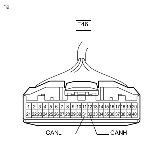
*a Front view of wire harness connector
(to Combination Meter Assembly)
Disconnect the E46 combination meter assembly connector.
-
Measure the resistance according to the value(s) in the table below.
Standard Resistance Tester Connection Condition Specified Condition E46-32 (CANH) - E46-31 (CANL) Cable disconnected from negative (-) battery terminal 108 to 132 Ω Result Result Proceed to OK A NG (for 1NR-FE, 1ZR-FAE, 1ZR-FE or 2ZR-FE) B NG (for 1ND-TV without Glow Plug Controller) C NG (for 1ND-TV with Glow Plug Controller) D NG (for 1WW) E NG (for 8NR-FTS) F
A
REPLACE COMBINATION METER ASSEMBLY for Sedan Click here except Sedan Click here
C 
CHECK FOR OPEN IN CAN BUS LINES (ECM) Click here
D
CHECK FOR OPEN IN CAN BUS LINES (ECM) Click here
E
CHECK FOR OPEN IN CAN BUS LINES (ECM) Click here
F
CHECK FOR OPEN IN CAN BUS LINES (ECM) Click here
B
-
-
CHECK FOR OPEN IN CAN BUS LINES (ECM)
-
Reconnect the E46 combination meter assembly connector.
-
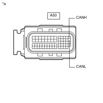
*a Front view of wire harness connector
(to ECM)
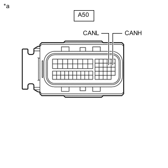
Disconnect the A50 ECM connector.
-
Measure the resistance according to the value(s) in the table below.
Standard Resistance Tester Connection Condition Specified Condition A50-13 (CANH) - A50-26 (CANL) Cable disconnected from negative (-) battery terminal 108 to 132 Ω Result Result Proceed to OK (for 1NR-FE) A OK (for 1ZR-FAE) B OK (for 1ZR-FE) C OK (for 2ZR-FE) D NG (for Sedan) E NG (except Sedan) F
A
REPLACE ECM Click here
B
REPLACE ECM Click here
C
REPLACE ECM Click here
D
REPLACE ECM Click here
E
GO TO STEP 6 Click here
F
GO TO STEP 10 Click here
-
-
CHECK FOR OPEN IN CAN BUS LINES (ECM)
-
Reconnect the E46 combination meter assembly connector.
-
*a Front view of wire harness connector
(to ECM)
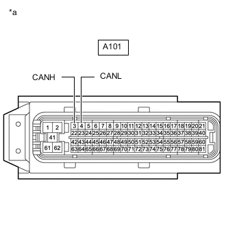
Disconnect the A101 ECM connector.
-
Measure the resistance according to the value(s) in the table below.
Standard Resistance Tester Connection Condition Specified Condition A101-3 (CANH) - A101-4 (CANL) Cable disconnected from negative (-) battery terminal 108 to 132 Ω Result Result OK NG
OK
REPLACE ECM Click here
NG
GO TO STEP 6 Click here
-
-
CHECK FOR OPEN IN CAN BUS LINES (ECM)
-
Reconnect the E46 combination meter assembly connector.
-
*a Front view of wire harness connector
(to ECM)
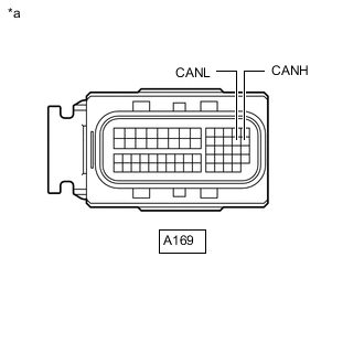
Disconnect the A169 ECM connector.
-
Measure the resistance according to the value(s) in the table below.
Standard Resistance Tester Connection Condition Specified Condition A169-26 (CANH) - A169-25 (CANL) Cable disconnected from negative (-) battery terminal 108 to 132 Ω Result Result Proceed to OK A NG (for Sedan) B NG (except Sedan) C
A
REPLACE ECM Click here
C
GO TO STEP 10 Click here
B
-
-
CHECK FOR OPEN IN CAN BUS LINES (NO. 3 CAN JUNCTION CONNECTOR)
-
Reconnect the A50, A101, A169 or A173 ECM connector.
-
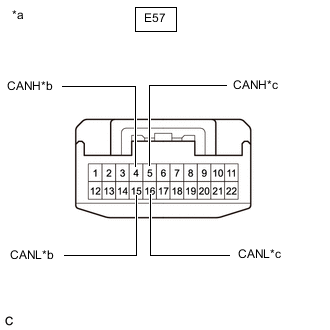
*a Front view of wire harness connector
(to No. 3 CAN Junction Connector)
*b to Combination Meter Assembly *c to No. 1 CAN Junction Connector Disconnect the E57 No. 3 CAN junction connector.
-
Measure the resistance according to the value(s) in the table below.
Standard Resistance Tester Connection Condition Specified Condition Connected to E57-4 (CANH) - E57-15 (CANL) Cable disconnected from negative (-) battery terminal 108 to 132 Ω Combination meter assembly E57-5 (CANH) - E57-16 (CANL) Cable disconnected from negative (-) battery terminal 108 to 132 Ω No. 1 CAN junction connector Result Result Proceed to OK A NG (Combination meter assembly main lines) B NG (No. 1 CAN junction connector main lines) C
A
REPLACE NO. 3 CAN JUNCTION CONNECTOR
B
REPAIR OR REPLACE CAN MAIN BUS LINES OR CONNECTOR (COMBINATION METER ASSEMBLY - NO. 3 CAN JUNCTION CONNECTOR)
C
-
-
CHECK FOR OPEN IN CAN BUS LINES (NO. 1 CAN JUNCTION CONNECTOR)
-
Reconnect the E57 No. 3 CAN junction connector.
-
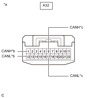
*a Front view of wire harness connector
(to No. 1 CAN Junction Connector)
*b to No. 3 CAN Junction Connector *c to ECM Disconnect the A32 No. 1 CAN junction connector.
-
Measure the resistance according to the value(s) in the table below.
Standard Resistance Tester Connection Condition Specified Condition Connected to A32-1 (CANH) - A32-12 (CANL) Cable disconnected from negative (-) battery terminal 108 to 132 Ω No. 3 CAN junction connector A32-6 (CANH) - A32-17 (CANL) Cable disconnected from negative (-) battery terminal 108 to 132 Ω ECM Result Result Proceed to OK A NG (No. 3 CAN junction connector main lines) B NG (ECM main lines) C
A
REPLACE NO. 1 CAN JUNCTION CONNECTOR
B
REPAIR OR REPLACE CAN MAIN BUS LINES OR CONNECTOR (NO. 1 CAN JUNCTION CONNECTOR - NO. 3 CAN JUNCTION CONNECTOR)
C
REPAIR OR REPLACE CAN MAIN BUS LINES OR CONNECTOR (ECM - NO. 1 CAN JUNCTION CONNECTOR)
-
-
CHECK FOR OPEN IN CAN BUS LINES (ECM)
-
Reconnect the E46 combination meter assembly connector.
-
*a Front view of wire harness connector
(to ECM)
Disconnect the A50 ECM connector.
-
Measure the resistance according to the value(s) in the table below.
Standard Resistance Tester Connection Condition Specified Condition A50-26 (CANH) - A50-25 (CANL) Cable disconnected from negative (-) battery terminal 108 to 132 Ω Result Result OK NG
OK
REPLACE ECM Click here
NG
GO TO STEP 10 Click here
-
-
CHECK FOR OPEN IN CAN BUS LINES (ECM)
-
Reconnect the E46 combination meter assembly connector.
-
*a Front view of wire harness connector
(to ECM)
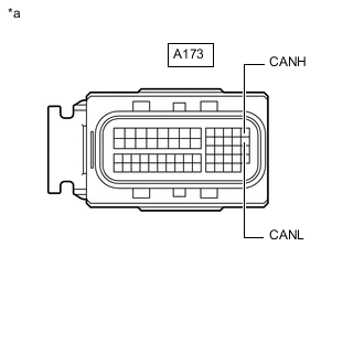
Disconnect the A173 ECM connector.
-
Measure the resistance according to the value(s) in the table below.
Standard Resistance Tester Connection Condition Specified Condition A173-13 (CANH) - A173-26 (CANL) Cable disconnected from negative (-) battery terminal 108 to 132 Ω Result Result OK NG
OK
REPLACE ECM Click here
NG
-
-
CHECK FOR OPEN IN CAN BUS LINES (NO. 3 CAN JUNCTION CONNECTOR)
-
Reconnect the A50, A169 or A173 ECM connector.
-
*a Front view of wire harness connector
(to No. 3 CAN Junction Connector)
*b to Combination Meter Assembly *c to No. 4 CAN Junction Connector Disconnect the E57 No. 3 CAN junction connector.
-
Measure the resistance according to the value(s) in the table below.
Standard Resistance Tester Connection Condition Specified Condition Connected to E57-4 (CANH) - E57-15 (CANL) Cable disconnected from negative (-) battery terminal 108 to 132 Ω Combination meter assembly E57-5 (CANH) - E57-16 (CANL) Cable disconnected from negative (-) battery terminal 108 to 132 Ω No. 4 CAN junction connector Result Result Proceed to OK A NG (Combination meter assembly main lines) B NG (No. 4 CAN junction connector main lines) C
A
REPLACE NO. 3 CAN JUNCTION CONNECTOR
B
REPAIR OR REPLACE CAN MAIN BUS LINES OR CONNECTOR (COMBINATION METER ASSEMBLY - NO. 3 CAN JUNCTION CONNECTOR)
C
-
-
CHECK FOR OPEN IN CAN BUS LINES (NO. 4 CAN JUNCTION CONNECTOR)
-
Reconnect the E57 No. 3 CAN junction connector.
-

*a Front view of wire harness connector
(to No. 4 CAN Junction Connector)
*b to No. 3 CAN Junction Connector *c to ECM Disconnect the A174 No. 4 CAN junction connector.
-
Measure the resistance according to the value(s) in the table below.
Standard Resistance Tester Connection Condition Specified Condition Connected to A174-1 (CANH) - A174-12 (CANL) Cable disconnected from negative (-) battery terminal 108 to 132 Ω No. 3 CAN junction connector A174-6 (CANH) - A174-17 (CANL) Cable disconnected from negative (-) battery terminal 108 to 132 Ω ECM Result Result Proceed to OK A NG (No. 3 CAN junction connector main lines) B NG (ECM main lines) C
A
REPLACE NO. 4 CAN JUNCTION CONNECTOR
B
REPAIR OR REPLACE CAN MAIN BUS LINES OR CONNECTOR (NO. 3 CAN JUNCTION CONNECTOR - NO. 4 CAN JUNCTION CONNECTOR)
C
REPAIR OR REPLACE CAN MAIN BUS LINES OR CONNECTOR (ECM - NO. 4 CAN JUNCTION CONNECTOR)
-