CAN COMMUNICATION SYSTEM(w/o Central Gateway ECU) ECM Communication Stop Mode
DESCRIPTION
| Detection Item | Symptom | Trouble Area |
|---|---|---|
| ECM Communication Stop Mode | Either condition is met:
|
|
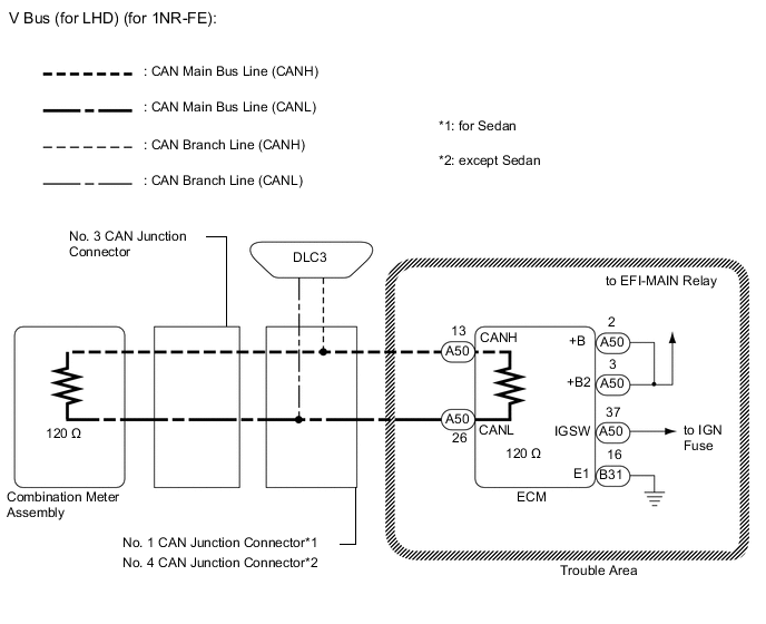
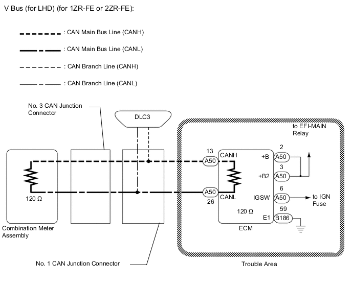
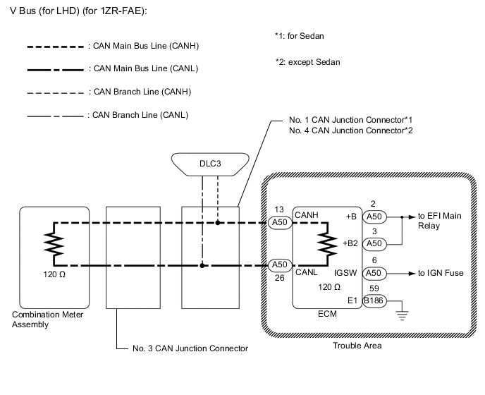
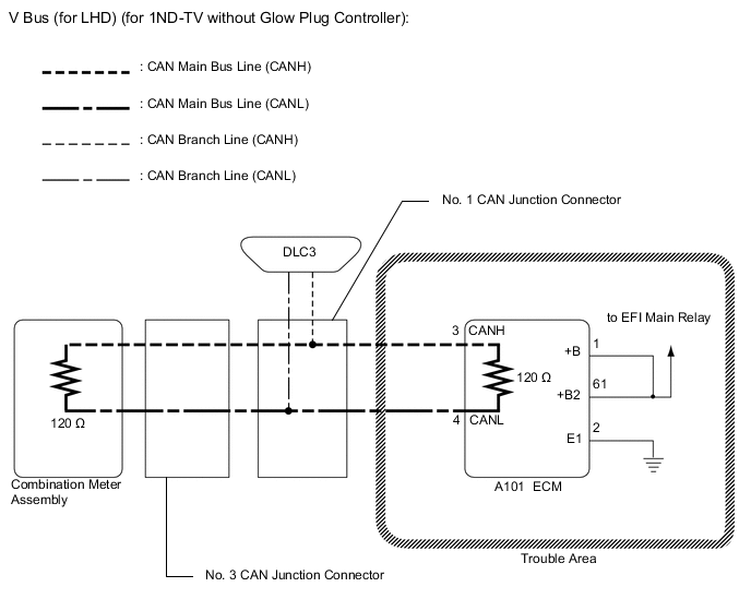
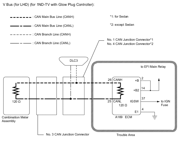
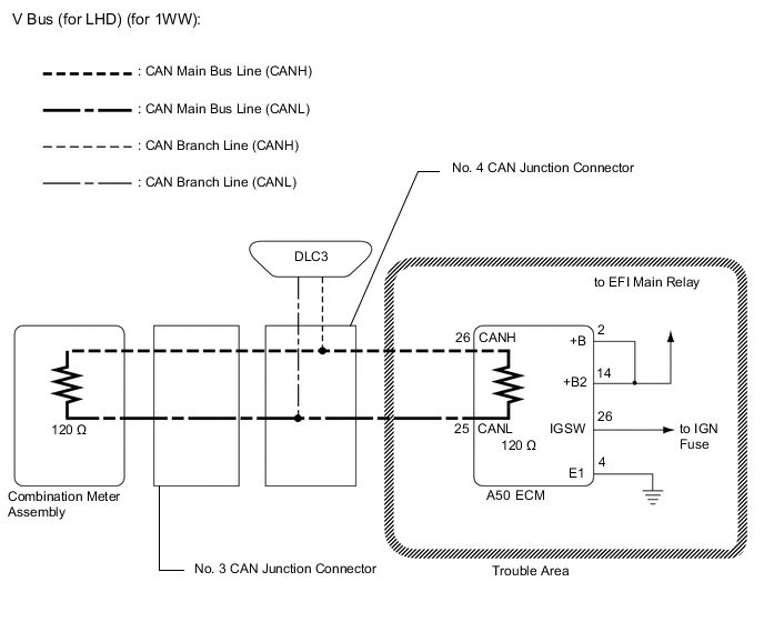
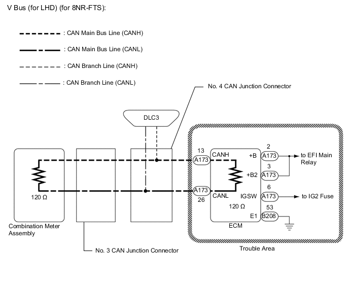
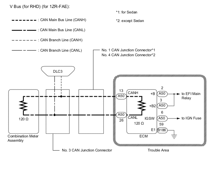
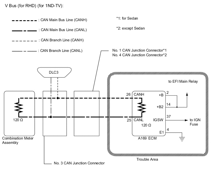
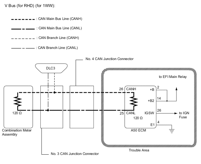
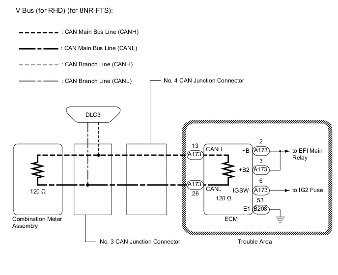
WIRING DIAGRAM

CAUTION / NOTICE / HINT
Note
-
Before measuring the resistance of the CAN bus, turn the ignition switch off and leave the vehicle for 1 minute or more without operating the key or any switches, or opening or closing the doors. After that, disconnect the cable from the negative (-) battery terminal and leave the vehicle for 1 minute or more before measuring the resistance.
-
After turning the ignition switch off, waiting time may be required before disconnecting the cable from the negative (-) battery terminal. Therefore, make sure to read the disconnecting the cable from the negative (-) battery terminal notices before proceeding with work.
-
Because the order of diagnosis is important to allow correct diagnosis, make sure to begin troubleshooting using How to Proceed with Troubleshooting when CAN communication system related DTCs are output.
-
After performing repairs, perform the DTC check procedure and confirm that the DTCs are not output again.
-
DTC check procedure: Turn the ignition switch to ON and wait 20 seconds or more, and then drive the vehicle at a speed of 20 km/h (12 mph) or more.
-
After the repair, perform the CAN bus check and check that all the ECUs and sensors connected to the CAN communication system are displayed.
-
Inspect the fuses for circuits related to this system before performing the following procedure.
Tech Tips
-
Operating the ignition switch, any other switches or a door triggers related ECU and sensor communication on the CAN. This communication will cause the resistance value to change.
-
Even after DTCs are cleared, if a DTC is stored again after driving the vehicle for a while, the malfunction may be occurring due to vibration of the vehicle. In such a case, wiggling the ECUs or wire harness while performing the inspection below may help determine the cause of the malfunction.
PROCEDURE
-
CHECK VEHICLE TYPE
-
Check vehicle type.
Result Result Proceed to for 1NR-FE, 1ZR-FAE, 1ZR-FE or 2ZR-FE A for 1ND-TV without Glow Plug Controller B for 1ND-TV with Glow Plug Controller C for 1WW D for 8NR-FTS E
B 
CHECK FOR OPEN IN CAN BUS LINES (ECM MAIN LINE) Click here
C
CHECK FOR OPEN IN CAN BUS LINES (ECM MAIN LINE) Click here
D
CHECK FOR OPEN IN CAN BUS LINES (ECM MAIN LINE) Click here
E
CHECK FOR OPEN IN CAN BUS LINES (ECM MAIN LINE) Click here
A 
-
-
CHECK FOR OPEN IN CAN BUS LINES (ECM MAIN LINE)
-
Disconnect the cable from the negative (-) battery terminal.
-
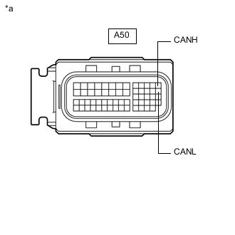
*a Front view of wire harness connector
(to ECM)
Disconnect the A50 ECM connector.
-
Measure the resistance according to the value(s) in the table below.
Standard Resistance Tester Connection Condition Specified Condition A50-13 (CANH) - A50-26 (CANL) Cable disconnected from negative (-) battery terminal 108 to 132 Ω Result Result OK NG
NG 
REPAIR OR REPLACE CAN MAIN BUS LINE OR CONNECTOR (ECM MAIN LINE)
OK
-
-
CHECK ECM POWER SOURCE CIRCUIT
-
Check the ECM power source circuit.
-
for 1NR-FE
-
for 1ZR-FAE
-
for 1ZR-FE
-
for 2ZR-FE
Result Result Proceed to OK (for 1NR-FE) A OK (for 1ZR-FAE) B OK (for 1ZR-FE) C OK (for 2ZR-FE) D NG E -
A
REPLACE ECM Click here
B
REPLACE ECM Click here
C
REPLACE ECM Click here
D
REPLACE ECM Click here
E
REPAIR OR REPLACE HARNESS OR CONNECTOR (POWER SOURCE CIRCUIT)
-
-
CHECK FOR OPEN IN CAN BUS LINES (ECM MAIN LINE)
-
Disconnect the cable from the negative (-) battery terminal.
-
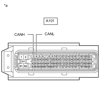
*a Front view of wire harness connector
(to ECM)
Disconnect the A101 ECM connector.
-
Measure the resistance according to the value(s) in the table below.
Standard Resistance Tester Connection Condition Specified Condition A101-3 (CANH) - A101-4 (CANL) Cable disconnected from negative (-) battery terminal 108 to 132 Ω Result Result OK NG
NG
REPAIR OR REPLACE CAN MAIN BUS LINE OR CONNECTOR (ECM MAIN LINE)
OK
-
-
CHECK ECM POWER SOURCE CIRCUIT
-
Check the ECM power source circuit.
Result Result OK NG
OK
REPLACE ECM Click here
NG
REPAIR OR REPLACE HARNESS OR CONNECTOR (POWER SOURCE CIRCUIT)
-
-
CHECK FOR OPEN IN CAN BUS LINES (ECM MAIN LINE)
-
Disconnect the cable from the negative (-) battery terminal.
-
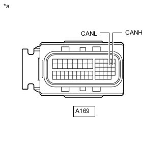
*a Front view of wire harness connector
(to ECM)
Disconnect the A169 ECM connector.
-
Measure the resistance according to the value(s) in the table below.
Standard Resistance Tester Connection Condition Specified Condition A169-26 (CANH) - A169-25 (CANL) Cable disconnected from negative (-) battery terminal 108 to 132 Ω Result Result OK NG
NG
REPAIR OR REPLACE CAN MAIN BUS LINE OR CONNECTOR (ECM MAIN LINE)
OK
-
-
CHECK ECM POWER SOURCE CIRCUIT
-
Check the ECM power source circuit.
Result Result OK NG
OK
REPLACE ECM Click here
NG
REPAIR OR REPLACE HARNESS OR CONNECTOR (POWER SOURCE CIRCUIT)
-
-
CHECK FOR OPEN IN CAN BUS LINES (ECM MAIN LINE)
-
Disconnect the cable from the negative (-) battery terminal.
-
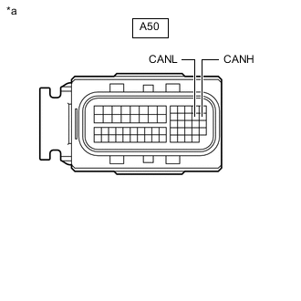
*a Front view of wire harness connector
(to ECM)
Disconnect the A50 ECM connector.
-
Measure the resistance according to the value(s) in the table below.
Standard Resistance Tester Connection Condition Specified Condition A50-26 (CANH) - A50-25 (CANL) Cable disconnected from negative (-) battery terminal 108 to 132 Ω Result Result OK NG
NG
REPAIR OR REPLACE CAN MAIN BUS LINE OR CONNECTOR (ECM MAIN LINE)
OK
-
-
CHECK ECM POWER SOURCE CIRCUIT
-
Check the ECM power source circuit.
Result Result OK NG
OK
REPLACE ECM Click here
NG
REPAIR OR REPLACE HARNESS OR CONNECTOR (POWER SOURCE CIRCUIT)
-
-
CHECK FOR OPEN IN CAN BUS LINES (ECM MAIN LINE)
-
Disconnect the cable from the negative (-) battery terminal.
-
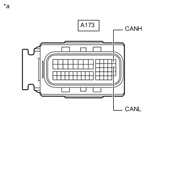
*a Front view of wire harness connector
(to ECM)
Disconnect the A173 ECM connector.
-
Measure the resistance according to the value(s) in the table below.
Standard Resistance Tester Connection Condition Specified Condition A173-13 (CANH) - A173-26 (CANL) Cable disconnected from negative (-) battery terminal 108 to 132 Ω Result Result OK NG
NG
REPAIR OR REPLACE CAN MAIN BUS LINE OR CONNECTOR (ECM MAIN LINE)
OK
-
-
CHECK ECM POWER SOURCE CIRCUIT
-
Check the ECM power source circuit.
Result Result OK NG
OK
REPLACE ECM Click here
NG
REPAIR OR REPLACE HARNESS OR CONNECTOR (POWER SOURCE CIRCUIT)
-