CAN COMMUNICATION SYSTEM(w/o Central Gateway ECU) Check CAN Bus Lines for Short Circuit (LHD Models)
DESCRIPTION
There may be a short circuit between the V bus main lines and/or CAN branch lines when the resistance between terminals 6 (CANH) and 14 (CANL) of the DLC3 is below 54 Ω.
| Symptom | Trouble Area |
|---|---|
| Resistance between terminals 6 (CANH) and 14 (CANL) of the DLC3 is below 54 Ω. |
|
-
*1: w/ Entry and Start System
-
*2: w/ VSC
-
*3: for Radio and Display Type
-
*4: w/ Air Conditioning System
-
*5: w/ Simple Intelligent Parking Assist System
-
*6: w/ Stop and Start System
-
*7: for Sedan with Automatic Headlight Beam Level Control System
-
*8: except Sedan with Automatic Headlight Beam Level Control System
-
*9: w/ Toyota Safety Sense
-
*10: w/ Manual (SOS) Switch
-
*11: for Sedan
-
*12: except Sedan
WIRING DIAGRAM
CAUTION / NOTICE / HINT
Note
-
Before measuring the resistance of the CAN bus, turn the ignition switch off and leave the vehicle for 1 minute or more without operating the key or any switches, or opening or closing the doors. After that, disconnect the cable from the negative (-) battery terminal and leave the vehicle for 1 minute or more before measuring the resistance.
-
After turning the ignition switch off, waiting time may be required before disconnecting the cable from the negative (-) battery terminal. Therefore, make sure to read the disconnecting the cable from the negative (-) battery terminal notices before proceeding with work.
-
Because the order of diagnosis is important to allow correct diagnosis, make sure to begin troubleshooting using How to Proceed with Troubleshooting when CAN communication system related DTCs are output.
-
After performing repairs, perform the DTC check procedure and confirm that the DTCs are not output again.
-
DTC check procedure: Turn the ignition switch to ON and wait at least 31 seconds, and then drive the vehicle at a speed of 20 km/h (12 mph) or more.
-
After the repair, perform the CAN bus check and check that all the ECUs and sensors connected to the CAN communication system are displayed.
Tech Tips
-
Operating the ignition switch, any other switches or a door triggers related ECU and sensor communication on the CAN. This communication will cause the resistance value to change.
-
Even after DTCs are cleared, if a DTC is stored again after driving the vehicle for a while, the malfunction may be occurring due to vibration of the vehicle. In such a case, wiggling the ECUs or wire harness while performing the inspection below may help determine the cause of the malfunction.
PROCEDURE
-
CHECK FOR SHORT IN CAN BUS LINES (COMBINATION METER ASSEMBLY)
-
Disconnect the cable from the negative (-) battery terminal.
-

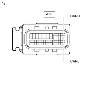
*a Front view of wire harness connector
(to Combination Meter Assembly)
Disconnect the E46 combination meter assembly connector.
-
Measure the resistance according to the value(s) in the table below.
Standard Resistance Tester Connection Condition Specified Condition E46-32 (CANH) - E46-31 (CANL) Cable disconnected from negative (-) battery terminal 108 to 132 Ω Result Result Proceed to OK A NG (for 1NR-FE, 1ZR-FAE, 1ZR-FE or 2ZR-FE) B NG (for 1ND-TV with Glow Plug Controller) C NG (for 1WW) D NG (for 8NR-FTS) E
A 
REPLACE COMBINATION METER ASSEMBLY for Sedan Click here except Sedan Click here
C 
CHECK FOR SHORT IN CAN BUS LINES (ECM) Click here
D
CHECK FOR SHORT IN CAN BUS LINES (ECM) Click here
E
CHECK FOR SHORT IN CAN BUS LINES (ECM) Click here
B 
-
-
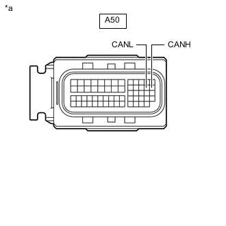
CHECK FOR SHORT IN CAN BUS LINES (ECM)
-
Reconnect the E46 combination meter assembly connector.
-
*a Front view of wire harness connector
(to ECM)
Disconnect the A50 ECM connector.
-
Measure the resistance according to the value(s) in the table below.
Standard Resistance Tester Connection Condition Specified Condition A50-13 (CANH) - A50-26 (CANL) Cable disconnected from negative (-) battery terminal 108 to 132 Ω Result Result Proceed to OK (for 1NR-FE) A OK (for 1ZR-FAE) B OK (for 1ZR-FE) C OK (for 2ZR-FE) D NG (for Sedan) E NG (except Sedan) F
A
REPLACE ECM Click here
B
REPLACE ECM Click here
C
REPLACE ECM Click here
D
REPLACE ECM Click here
E
GO TO STEP 4 Click here
F
GO TO STEP 8 Click here
-
-
CHECK FOR SHORT IN CAN BUS LINES (ECM)
-
Reconnect the E46 combination meter assembly connector.
-
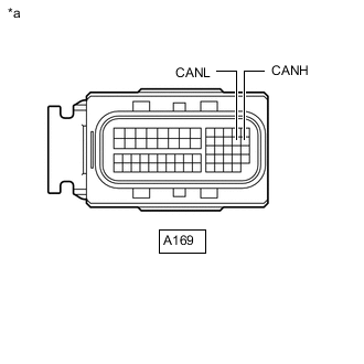
*a Front view of wire harness connector
(to ECM)
Disconnect the A169 ECM connector.
-
Measure the resistance according to the value(s) in the table below.
Standard Resistance Tester Connection Condition Specified Condition A169-26 (CANH) - A169-25 (CANL) Cable disconnected from negative (-) battery terminal 108 to 132 Ω Result Result Proceed to OK A NG (for Sedan) B NG (except Sedan) C
A
REPLACE ECM Click here
C
GO TO STEP 8 Click here
B
-
-
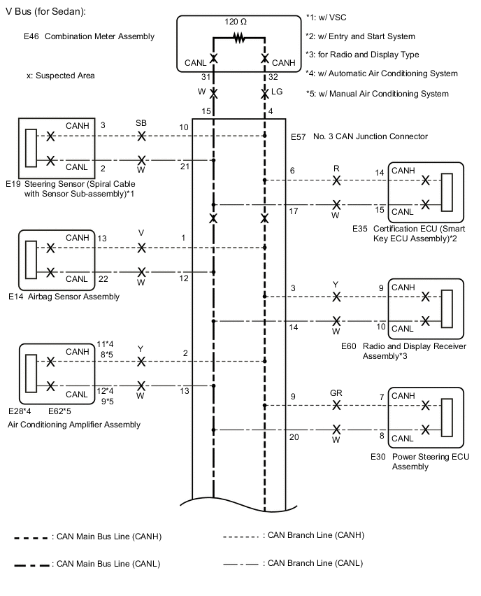
CHECK FOR SHORT IN CAN BUS LINES (NO. 3 CAN JUNCTION CONNECTOR)
-
Reconnect the A50 or A169 ECM connector.
-
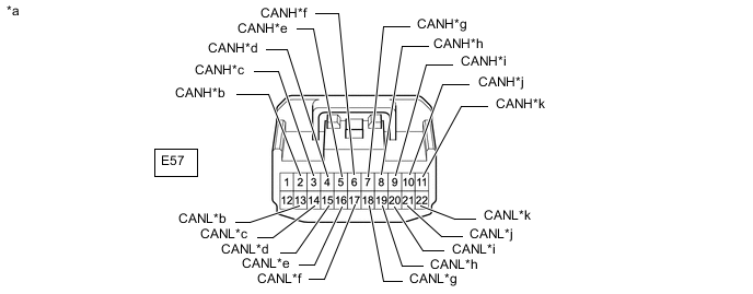
Disconnect the E57 No. 3 CAN junction connector.
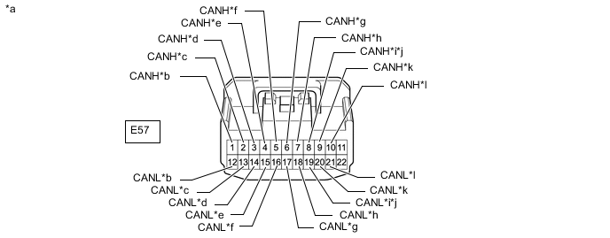
*a Front view of wire harness connector
(to No. 3 CAN Junction Connector)
*b to Airbag Sensor Assembly *c to Air Conditioning Amplifier Assembly
(w/ Air Conditioning System)
*d to Radio and Display Receiver Assembly
(for Radio and Display Type)
*e to Combination Meter Assembly *f to No. 1 CAN Junction Connector *g to Certification ECU (Smart Key ECU Assembly)
(w/ Entry and Start System)
*h to Clearance Warning ECU Assembly
(w/ Simple Intelligent Parking Assist System)
*i to Engine Stop and Start ECU
(w/ Stop and Start System)
*j to Telematics Transceiver
(w/ Manual (SOS) Switch)
*k to Power Steering ECU Assembly *l to Steering Sensor (Spiral Cable with Sensor Sub-assembly)
(w/ VSC)
-
Measure the resistance according to the value(s) in the table below.
Standard Resistance Tester Connection Condition Specified Condition Connected to E57-1 (CANH) - E57-12 (CANL) Cable disconnected from negative (-) battery terminal 200 Ω or higher Airbag sensor assembly E57-2 (CANH) - E57-13 (CANL) Cable disconnected from negative (-) battery terminal 200 Ω or higher Air conditioning amplifier assembly*1 E57-3 (CANH) - E57-14 (CANL) Cable disconnected from negative (-) battery terminal 200 Ω or higher Radio and display receiver assembly*2 E57-4 (CANH) - E57-15 (CANL) Cable disconnected from negative (-) battery terminal 108 to 132 Ω Combination meter assembly E57-5 (CANH) - E57-16 (CANL) Cable disconnected from negative (-) battery terminal 108 to 132 Ω No. 1 CAN junction connector E57-6 (CANH) - E57-17 (CANL) Cable disconnected from negative (-) battery terminal 200 Ω or higher Certification ECU (smart key ECU assembly)*3 E57-7 (CANH) - E57-18 (CANL) Cable disconnected from negative (-) battery terminal 200 Ω or higher Clearance warning ECU assembly*4 E57-8 (CANH) - E57-19 (CANL) Cable disconnected from negative (-) battery terminal 200 Ω or higher Engine stop and start ECU*5 E57-8 (CANH) - E57-19 (CANL) Cable disconnected from negative (-) battery terminal 200 Ω or higher Telematics transceiver*6 E57-9 (CANH) - E57-20 (CANL) Cable disconnected from negative (-) battery terminal 200 Ω or higher Power steering ECU assembly E57-10 (CANH) - E57-21 (CANL) Cable disconnected from negative (-) battery terminal 200 Ω or higher Steering sensor (spiral cable with sensor sub-assembly)*7
-
*1: w/ Air Conditioning System
-
*2: for Radio and Display Type
-
*3: w/ Entry and Start System
-
*4: w/ Simple Intelligent Parking Assist System
-
*5: w/ Stop and Start System
-
*6: w/ Manual (SOS) Switch
-
*7: w/ VSC
Result Result Proceed to OK A NG (No. 1 CAN junction connector main lines) B NG (ECU or sensor branch lines) C NG (Combination meter assembly main lines) D -
A
REPLACE NO. 3 CAN JUNCTION CONNECTOR
C
GO TO STEP 10 Click here
D
REPAIR OR REPLACE CAN MAIN BUS LINES OR CONNECTOR (COMBINATION METER ASSEMBLY - NO. 3 CAN JUNCTION CONNECTOR)
B
-
-
CHECK FOR SHORT IN CAN BUS LINES (NO. 1 CAN JUNCTION CONNECTOR)
-
Disconnect the A32 No. 1 CAN junction connector.
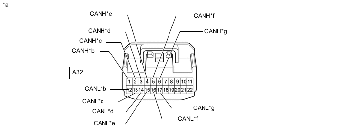
*a Front view of wire harness connector
(to No. 1 CAN Junction Connector)
*b to No. 3 CAN Junction Connector *c to DLC3 *d to Main Body ECU (Multiplex Network Body ECU) *e to Headlight Leveling ECU Assembly
(w/ Automatic Headlight Beam Level Control System)
*f to Brake Actuator Assembly *g to ECM - - -
Measure the resistance according to the value(s) in the table below.
Standard Resistance Tester Connection Condition Specified Condition Connected to A32-1 (CANH) - A32-12 (CANL) Cable disconnected from negative (-) battery terminal 1 MΩ or higher No. 3 CAN junction connector A32-2 (CANH) - A32-13 (CANL) Cable disconnected from negative (-) battery terminal 1 MΩ or higher DLC3 A32-3 (CANH) - A32-14 (CANL) Cable disconnected from negative (-) battery terminal 200 Ω or higher Main body ECU (multiplex network body ECU) A32-4 (CANH) - A32-15 (CANL) Cable disconnected from negative (-) battery terminal 200 Ω or higher Headlight leveling ECU assembly* A32-5 (CANH) - A32-16 (CANL) Cable disconnected from negative (-) battery terminal 200 Ω or higher Brake actuator assembly A32-6 (CANH) - A32-17 (CANL) Cable disconnected from negative (-) battery terminal 108 to 132 Ω ECM
-
*: w/ Automatic Headlight Beam Level Control System
Result Result Proceed to OK A NG (No. 3 CAN junction connector main lines) B NG (ECU or sensor branch lines) C NG (ECM main lines) D NG (DLC3 branch lines) E -
A
REPLACE NO. 1 CAN JUNCTION CONNECTOR
B
REPAIR OR REPLACE CAN MAIN BUS LINES OR CONNECTOR (NO. 1 CAN JUNCTION CONNECTOR - NO. 3 CAN JUNCTION CONNECTOR)
C
GO TO STEP 10 Click here
D
REPAIR OR REPLACE CAN MAIN BUS LINES OR CONNECTOR (ECM - NO. 1 CAN JUNCTION CONNECTOR)
E
REPAIR OR REPLACE CAN BRANCH LINE CONNECTED TO DLC3
-
-
CHECK FOR SHORT IN CAN BUS LINES (ECM)
-
Reconnect the E46 combination meter assembly connector.
-
*a Front view of wire harness connector
(to ECM)
Disconnect the A50 ECM connector.
-
Measure the resistance according to the value(s) in the table below.
Standard Resistance Tester Connection Condition Specified Condition A50-26 (CANH) - A50-25 (CANL) Cable disconnected from negative (-) battery terminal 108 to 132 Ω Result Result OK NG
OK
REPLACE ECM Click here
NG
GO TO STEP 8 Click here
-
-
CHECK FOR SHORT IN CAN BUS LINES (ECM)
-
Reconnect the E46 combination meter assembly connector.
-
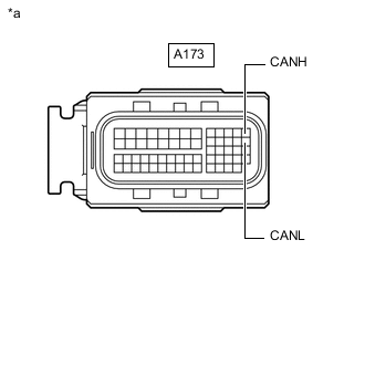
*a Front view of wire harness connector
(to ECM)
Disconnect the A173 ECM connector.
-
Measure the resistance according to the value(s) in the table below.
Standard Resistance Tester Connection Condition Specified Condition A173-13 (CANH) - A173-26 (CANL) Cable disconnected from negative (-) battery terminal 108 to 132 Ω Result Result OK NG
OK
REPLACE ECM Click here
NG
-
-
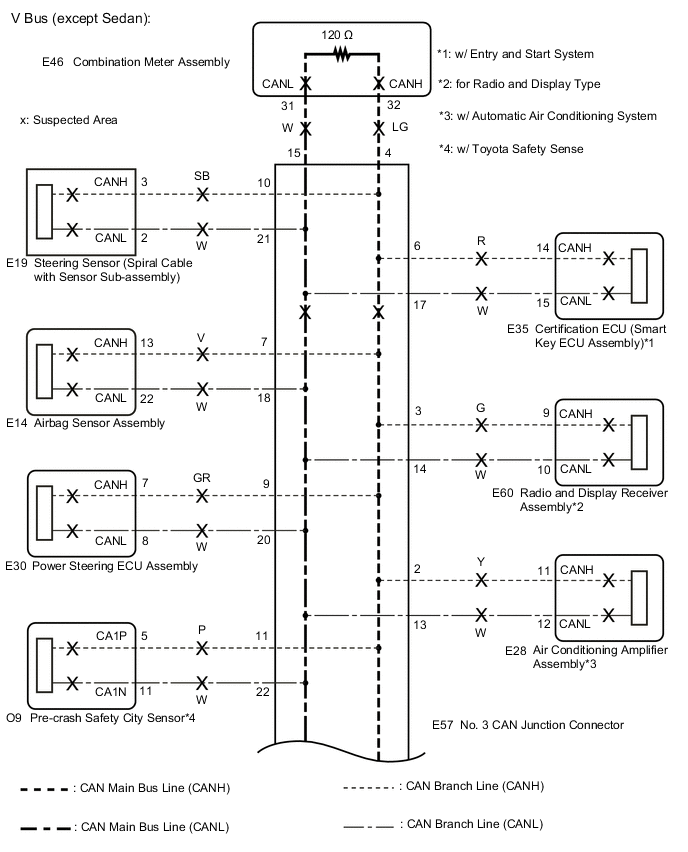
CHECK FOR SHORT IN CAN BUS LINES (NO. 3 CAN JUNCTION CONNECTOR)
-
Reconnect the A50, A169 or A173 ECM connector.
-
Disconnect the E57 No. 3 CAN junction connector.
*a Front view of wire harness connector
(to No. 3 CAN Junction Connector)
*b to Air Conditioning Amplifier Assembly
(w/ Automatic Air Conditioning System)
*c to Radio and Display Receiver Assembly
(for Radio and Display Type)
*d to Combination Meter Assembly *e to No. 4 CAN Junction Connector *f to Certification ECU (Smart Key ECU Assembly)
(w/ Entry and Start System)
*g to Airbag Sensor Assembly *h to Engine Stop and Start ECU
(w/ Stop and Start System)
*i to Power Steering ECU Assembly *j to Steering Sensor (Spiral Cable with Sensor Sub-assembly) *k to Pre-crash Safety City Sensor
(w/ Toyota Safety Sense)
- - -
Measure the resistance according to the value(s) in the table below.
Standard Resistance Tester Connection Condition Specified Condition Connected to E57-2 (CANH) - E57-13 (CANL) Cable disconnected from negative (-) battery terminal 200 Ω or higher Air conditioning amplifier assembly*1 E57-3 (CANH) - E57-14 (CANL) Cable disconnected from negative (-) battery terminal 200 Ω or higher Radio and display receiver assembly*2 E57-4 (CANH) - E57-15 (CANL) Cable disconnected from negative (-) battery terminal 108 to 132 Ω Combination meter assembly E57-5 (CANH) - E57-16 (CANL) Cable disconnected from negative (-) battery terminal 108 to 132 Ω No. 4 CAN junction connector E57-6 (CANH) - E57-17 (CANL) Cable disconnected from negative (-) battery terminal 200 Ω or higher Certification ECU (smart key ECU assembly)*3 E57-7 (CANH) - E57-18 (CANL) Cable disconnected from negative (-) battery terminal 200 Ω or higher Airbag sensor assembly E57-8 (CANH) - E57-19 (CANL) Cable disconnected from negative (-) battery terminal 200 Ω or higher Engine stop and start ECU*4 E57-9 (CANH) - E57-20 (CANL) Cable disconnected from negative (-) battery terminal 200 Ω or higher Power steering ECU assembly E57-10 (CANH) - E57-21 (CANL) Cable disconnected from negative (-) battery terminal 200 Ω or higher Steering sensor (spiral cable with sensor sub-assembly) E57-11 (CANH) - E57-22 (CANL) Cable disconnected from negative (-) battery terminal 200 Ω or higher Pre-crash safety city sensor*5
-
*1: w/ Automatic Air Conditioning System
-
*2: for Radio and Display Type
-
*3: w/ Entry and Start System
-
*4: w/ Stop and Start System
-
*5: w/ Toyota Safety Sense
Result Result Proceed to OK A NG (No. 4 CAN junction connector main lines) B NG (ECU or sensor branch lines) C NG (Combination meter assembly main lines) D -
A
REPLACE NO. 3 CAN JUNCTION CONNECTOR
C
GO TO STEP 10 Click here
D
REPAIR OR REPLACE CAN MAIN BUS LINES OR CONNECTOR (COMBINATION METER ASSEMBLY - NO. 3 CAN JUNCTION CONNECTOR)
B
-
-
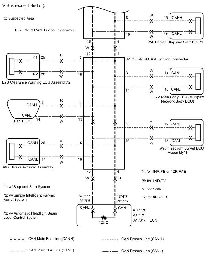
CHECK FOR SHORT IN CAN BUS LINES (NO. 4 CAN JUNCTION CONNECTOR)
-
Disconnect the A174 No. 4 CAN junction connector.
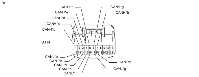
*a Front view of wire harness connector
(to No. 4 CAN Junction Connector)
*b to No. 3 CAN Junction Connector *c to DLC3 *d to Main Body ECU (Multiplex Network Body ECU) *e to Headlight Swivel ECU Assembly
(w/ Automatic Headlight Beam Level Control System)
*f to Brake Actuator Assembly *g to ECM *h to Clearance Warning ECU Assembly
(w/ Simple Intelligent Parking Assist System)
-
Measure the resistance according to the value(s) in the table below.
Standard Resistance Tester Connection Condition Specified Condition Connected to A174-1 (CANH) - A174-12 (CANL) Cable disconnected from negative (-) battery terminal 1 MΩ or higher No. 3 CAN junction connector A174-2 (CANH) - A174-13 (CANL) Cable disconnected from negative (-) battery terminal 1 MΩ or higher DLC3 A174-3 (CANH) - A174-14 (CANL) Cable disconnected from negative (-) battery terminal 200 Ω or higher Main body ECU (multiplex network body ECU) A174-4 (CANH) - A174-15 (CANL) Cable disconnected from negative (-) battery terminal 200 Ω or higher Headlight swivel ECU assembly*1 A174-5 (CANH) - A174-16 (CANL) Cable disconnected from negative (-) battery terminal 200 Ω or higher Brake actuator assembly A174-6 (CANH) - A174-17 (CANL) Cable disconnected from negative (-) battery terminal 108 to 132 Ω ECM A174-7 (CANH) - A174-18 (CANL) Cable disconnected from negative (-) battery terminal 200 Ω or higher Clearance warning ECU assembly*2
-
*1: w/ Automatic Headlight Beam Level Control System
-
*2: w/ Simple Intelligent Parking Assist System
Result Result Proceed to OK A NG (No. 3 CAN junction connector main lines) B NG (ECU or sensor branch lines) C NG (DLC3 branch lines) D NG (ECM main lines) E -
A
REPLACE NO. 4 CAN JUNCTION CONNECTOR
B
REPAIR OR REPLACE CAN MAIN BUS LINES OR CONNECTOR (NO. 3 CAN JUNCTION CONNECTOR - NO. 4 CAN JUNCTION CONNECTOR)
D
REPAIR OR REPLACE CAN BRANCH LINE CONNECTED TO DLC3
E
REPAIR OR REPLACE CAN MAIN BUS LINES OR CONNECTOR (ECM - NO. 4 CAN JUNCTION CONNECTOR)
C
-
-
CHECK FOR SHORT IN CAN BUS LINES (ECU, SENSOR)
-
Reconnect all wire harness connectors.
-
Disconnect the connector that includes terminals CANH and CANL from the ECU or sensor to which the short circuited branch line is connected.
-
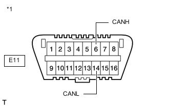
*1 DLC3 Measure the resistance according to the value(s) in the table below.
Standard Resistance Tester Connection Condition Specified Condition E11-6 (CANH) - E11-14 (CANL) Cable disconnected from negative (-) battery terminal 54 to 69 Ω Tech Tips
If the resistance becomes normal (between 54 and 69 Ω) when the connector is disconnected from the ECU or sensor, there may be a short in the ECU or sensor.
Result Result OK NG
OK
REPLACE CORRESPONDING ECU OR SENSOR
NG
REPAIR OR REPLACE CORRESPONDING ECU OR SENSOR BRANCH LINES OR CONNECTOR
-