ENGINE ASSEMBLY(w/ Glow Plug Controller) INSTALLATION
CAUTION / NOTICE / HINT
Note
-
As the engine assembly with transaxle is extremely heavy, the engine lifter may suddenly drop if the instructions listed in the repair manual are not followed. Therefore, always follow the instructions listed in the repair manual when performing this procedure.
-
When the transaxle is removed, be sure to use a new clutch release with bearing cylinder and new installation bolts. Removal of the transaxle allows the compressed clutch release with bearing cylinder to return to its original position, and dust could damage the seal of the clutch release with bearing cylinder, possibly causing clutch fluid leaks.
-
After replacing the engine assembly, perform both "Injector Compensation" and "Pilot Quantity Learning Values Reset" using the GTS.
PROCEDURE
-
INSTALL ENGINE HANGERS
-
REMOVE ENGINE FROM ENGINE STAND
-
Using a chain block and engine sling device, secure the engine assembly.
Note
-
Adjust the angle of the sling device carefully to prevent the engine assembly or engine hangers from deforming or becoming damaged.
-
Servicing an engine assembly while it is hanging is dangerous. This can be done only when installing/removing the engine assembly to/from an engine stand.
-
-
Remove the engine assembly from the engine stand.
-
-
INSTALL NO. 1 CRANKSHAFT POSITION SENSOR PLATE
-
INSTALL FLYWHEEL SUB-ASSEMBLY
-
INSTALL CRANK POSITION SENSOR
-
INSTALL CYLINDER BLOCK SIDE COVER
-
Install the cylinder block side cover and plate washer to the cylinder block sub-assembly with the bolt.
- Torque:
- 7.0 N*m { 71 kgf*cm, 62 in.*lbf }
-
-
INSTALL EXHAUST MANIFOLD
-
INSTALL TURBOCHARGER SUB-ASSEMBLY
-
INSTALL MANIFOLD STAY
-
INSTALL TURBOCHARGER STAY
-
INSTALL NO. 1 TURBO WATER PIPE SUB-ASSEMBLY
-
CONNECT NO. 2 TURBO WATER HOSE
-
CONNECT NO. 1 TURBO WATER HOSE
-
INSTALL MANIFOLD SUPPORT BRACKET
-
Install the manifold support bracket to the cylinder block sub-assembly with the 3 bolts.
- Torque:
- 37 N*m { 377 kgf*cm, 27 ft.*lbf }
-
-
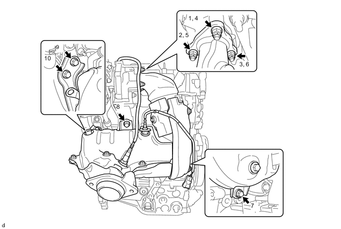
INSTALL NO. 2 EXHAUST MANIFOLD
-
Install a new outlet turbine elbow gasket to the turbocharger sub-assembly.
-
Temporarily install the No. 2 exhaust manifold to the turbocharger sub-assembly, No. 1 converter support bracket, manifold stay and No. 2 converter support bracket with the 4 bolts and 3 new nuts.
-
Fully tighten the 4 bolts and 3 nuts in the order shown in the illustration.
- Torque:
- Nut
- 26 N*m { 265 kgf*cm, 19 ft.*lbf }
- Bolt
- 37 N*m { 377 kgf*cm, 27 ft.*lbf }
-
Engage the clamp to connect the exhaust gas temperature sensor wire to the wiring harness clamp bracket.
-
Engage the claw to connect the exhaust gas temperature sensor wire connector to the wiring harness clamp bracket.
-
Install the wiring harness clamp bracket to the timing chain cover sub-assembly with the bolt.
- Torque:
- 9.0 N*m { 92 kgf*cm, 80 in.*lbf }
-
Connect the exhaust gas temperature sensor connector.
-
Connect the camshaft position sensor connector.
-
-
INSTALL DRIVE SHAFT HEAT INSULATOR SUB-ASSEMBLY
-
INSTALL NO. 4 MANIFOLD SUPPORT BRACKET
-
INSTALL NO. 5 MANIFOLD SUPPORT BRACKET
-
INSTALL NO. 2 VACUUM PIPE
-
INSTALL NO. 1 TURBO INSULATOR
-
INSTALL SENSOR BRACKET
-
INSTALL WIRING HARNESS CLAMP BRACKET
-
Install the wiring harness clamp bracket to the cylinder head cover sub-assembly.
-
-
INSTALL NO. 2 ENGINE COVER BRACKET
-
INSTALL DIFFERENTIAL PRESSURE SENSOR ASSEMBLY
-
INSTALL WIRING HARNESS CLAMP BRACKET
-
INSTALL NO. 1 WIRING HARNESS HEAT INSULATOR
-
INSTALL NO. 2 AIR TUBE
-
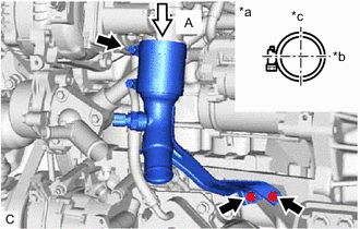
*a View (A) *b LH of Engine *c Rear of Engine Connect the No. 2 air tube to the diesel throttle body assembly with the hose clamp as shown in the illustration.
- Torque:
- 6.5 N*m { 66 kgf*cm, 58 in.*lbf }
Note
One minute after tightening the hose clamp, check that residual torque is 3.2 N*m (33 kgf*cm, 28 in.*lbf) or more.
-
Install the No. 2 air tube with the 2 bolts.
- Torque:
- 10 N*m { 102 kgf*cm, 7 ft.*lbf }
-
-
INSTALL ENGINE WIRE
-
Install the engine wire to the engine.
-
-
INSTALL CLUTCH DISC ASSEMBLY (for Manual Transaxle)
-
INSTALL CLUTCH COVER ASSEMBLY (for Manual Transaxle)
-
INSPECT AND ADJUST CLUTCH COVER ASSEMBLY (for Manual Transaxle)
-
INSTALL CLUTCH RELEASE WITH BEARING CYLINDER ASSEMBLY (for Manual Transaxle)
-
REMOVE CLUTCH RELEASE BLEEDER SUB-ASSEMBLY (for Manual Transaxle)
-
INSPECT CLUTCH PIPE LINE (for Manual Transaxle)
-
INSTALL CLUTCH RELEASE BLEEDER SUB-ASSEMBLY (for Manual Transaxle)
-
INSTALL BLEEDER TO ACCUMULATOR TUBE (for Manual Transaxle)
-
INSTALL MANUAL TRANSAXLE ASSEMBLY (for Manual Transaxle)
-
CONNECT WIRE HARNESS (for Manual Transaxle)
-
w/o Stop And Start System:
-
w/ Stop And Start System:
-
-
INSTALL STARTER ASSEMBLY (w/o Stop And Start System)
-
INSTALL STARTER ASSEMBLY (w/ Stop And Start System)
-
INSTALL NO. 1 AIR TUBE
-
INSTALL ENGINE MOUNTING INSULATOR LH
Tech Tips
Perform this procedure only when replacement of the engine mounting insulator LH is necessary.
-
Install the engine mounting insulator LH with the 4 bolts.
- Torque:
- 95 N*m { 969 kgf*cm, 70 ft.*lbf }
-
-
INSTALL ENGINE MOUNTING INSULATOR SUB-ASSEMBLY RH
Tech Tips
Perform this procedure only when replacement of the engine mounting insulator sub-assembly RH is necessary.
-
Install the engine mounting insulator sub-assembly RH with the 3 bolts.
- Torque:
- 95 N*m { 969 kgf*cm, 70 ft.*lbf }
-
Connect the cooler pipe clamp to the engine mounting insulator sub-assembly RH.
-
Install the cooler pipe clamp bracket to the engine mounting insulator sub-assembly with the bolt.
- Torque:
- 9.8 N*m { 100 kgf*cm, 87 in.*lbf }
-
Install the radiator reserve tank assembly with the 2 bolts.
- Torque:
- 5.0 N*m { 51 kgf*cm, 44 in.*lbf }
-
-
TEMPORARILY TIGHTEN REAR ENGINE MOUNTING INSULATOR
-
Temporarily install the rear engine mounting insulator with the through bolt.
-
-
TEMPORARILY TIGHTEN FRONT ENGINE MOUNTING INSULATOR
-
Temporarily install the front engine mounting insulator with the through bolt and nut.
-
-
INSTALL ENGINE ASSEMBLY WITH TRANSAXLE
-
Set the engine assembly with transaxle on an engine lifter.
Note
Place the height adjustment attachments and plate lift attachments under the engine assembly with transaxle.
-
Operate the engine lifter and lift the engine assembly with transaxle to the position where the engine mounting insulator LH and engine mounting insulator sub-assembly RH can be installed.
CAUTION:
Do not raise the engine more than necessary. If the engine is raised excessively, the vehicle may also be lifted up.
Note
While raising the engine assembly with transaxle into the vehicle, do not allow it to contact the vehicle.
-
Install the engine mounting insulator LH with the through bolt and nut.
- Torque:
- 56 N*m { 571 kgf*cm, 41 ft.*lbf }
Tech Tips
When tightening the through bolt, keep the nut from rotating.
-
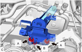
Install the engine mounting insulator sub-assembly RH with the 3 nuts.
- Torque:
- Nut (A)
- 95 N*m { 969 kgf*cm, 70 ft.*lbf }
- Nut (B)
- 52 N*m { 530 kgf*cm, 38 ft.*lbf }
-
Install the front crossmember sub-assembly with the 4 bolts.
- Torque:
- 99 N*m { 1010 kgf*cm, 73 ft.*lbf }
-
Connect the front engine mounting insulator to the front crossmember sub-assembly with the 2 bolts.
- Torque:
- 95 N*m { 969 kgf*cm, 70 ft.*lbf }
-
-
REMOVE ENGINE HANGERS
-
Remove the 2 bolts, No. 1 engine hanger and No. 2 engine hanger.
-
-
CONNECT NO. 1 CLUTCH HOSE (for Manual Transaxle)
-
Install a new clip to connect the No. 1 clutch hose to the flexible hose bracket.
-
Using a 10 mm union nut wrench, connect the No. 1 clutch hose to the accumulator to flexible hose tube.
- Torque:
- 15.2 N*m { 155 kgf*cm, 11 ft.*lbf }
Note
Use the formula to calculate special torque values for situations where a union nut wrench is combined with a torque wrench.
-
-
INSTALL FRONT SUSPENSION CROSSMEMBER SUB-ASSEMBLY
-
INSTALL FRONT SUSPENSION MEMBER REAR BRACE LH
-
INSTALL FRONT SUSPENSION MEMBER REAR BRACE RH
Tech Tips
Perform the same procedure as for the LH side.
-
INSTALL FRONT SUSPENSION MEMBER REINFORCEMENT LH
-
INSTALL FRONT SUSPENSION MEMBER REINFORCEMENT RH
-
INSTALL FRONT ENGINE MOUNTING BRACKET LOWER REINFORCEMENT
-
INSTALL REAR ENGINE MOUNTING INSULATOR
-
Install the rear engine mounting insulator with the through bolt.
- Torque:
- 95 N*m { 969 kgf*cm, 70 ft.*lbf }
-
-
INSTALL FRONT ENGINE MOUNTING INSULATOR
-
Install the front engine mounting insulator with the through bolt and nut.
- Torque:
- 85 N*m { 867 kgf*cm, 63 ft.*lbf }
Tech Tips
When tightening the through bolt, keep the nut from rotating.
-
-
INSTALL FRONT DRIVE SHAFT ASSEMBLY LH
-
INSTALL FRONT DRIVE SHAFT ASSEMBLY RH
-
INSTALL FRONT EXHAUST PIPE ASSEMBLY
-
INSTALL FRONT CENTER FLOOR BRACE SUB-ASSEMBLY
-
CONNECT NO. 1 STEERING COLUMN HOLE COVER SUB-ASSEMBLY
-
CONNECT NO. 2 STEERING INTERMEDIATE SHAFT ASSEMBLY
-
INSTALL COLUMN HOLE COVER SILENCER SHEET
-
INSTALL COMPRESSOR ASSEMBLY WITH PULLEY (w/ Air Conditioning System)
-
Using an E8 "TORX" socket wrench, temporarily install the compressor assembly with pulley with the 2 stud bolts.
- Torque:
- 9.8 N*m { 100 kgf*cm, 87 in.*lbf }
-
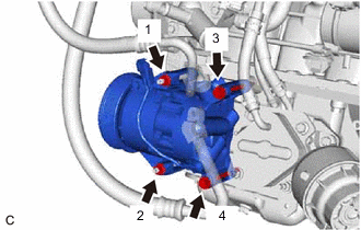
Install the compressor assembly with pulley with the 2 bolts and 2 nuts.
- Torque:
- 25 N*m { 255 kgf*cm, 18 ft.*lbf }
Tech Tips
Tighten the bolts and nuts in the order shown in the illustration to install the compressor assembly with pulley.
-
Connect the connector.
-
-
INSTALL V-RIBBED BELT
-
INSPECT V-RIBBED BELT
-
CONNECT OUTLET HEATER WATER HOSE
-
Connect the outlet heater water hose to the water by-pass pipe sub-assembly and slide the clip to secure it.
-
-
CONNECT INLET HEATER WATER HOSE A (w/o Combustion Type Power Heater)
-
Connect the inlet heater water hose A to the inlet heater water pipe A and slide the clip to secure it.
-
-
CONNECT INLET HEATER WATER HOSE D (w/ Combustion Type Power Heater)
-
Connect the inlet heater water hose D to the inlet heater water pipe A and slide the clip to secure it.
-
-
CONNECT NO. 1 RADIATOR HOSE
-
Connect the No. 1 radiator hose to the outlet water sub-assembly and slide the clip to secure it.
-
-
CONNECT NO. 2 RADIATOR HOSE
-
Connect the No. 2 radiator hose to the water inlet and slide the clip to secure it.
-
-
CONNECT WATER BY-PASS HOSE
-
Connect the water by-pass hose to the water inlet and slide the clip to secure it.
-
-
CONNECT UNION TO CONNECTOR TUBE HOSE
-
Connect the union to connector tube hose to the cylinder head cover sub-assembly and slide the clip to secure it.
-
-
CONNECT TRANSMISSION CONTROL CABLE ASSEMBLY (for Manual Transaxle)
-
Install the transmission control cable assembly to the rear engine mounting bracket with the bolt.
- Torque:
- 5.0 N*m { 51 kgf*cm, 44 in.*lbf }
-
Install the 2 transmission control cable assemblies to the control cable bracket assembly with 2 new clips.
-
Install the 2 transmission control cable assemblies to the manual transaxle assembly with the 2 clips.
-
-
INSTALL INTERCOOLER AIR HOSE
-
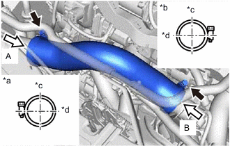
*a View (A) *b View (B) *c Top of Engine *d Front of Engine Install the intercooler air hose with the 2 hose clamps as shown in the illustration.
- Torque:
- 6.5 N*m { 66 kgf*cm, 58 in.*lbf }
Note
One minute after tightening the hose clamps, check that the residual torque is 3.2 N*m (33 kgf*cm, 28 in.*lbf) or more.
-
-
INSTALL NO. 3 AIR HOSE
-
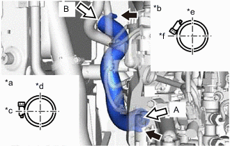
*a View (A) *b View (B) *c LH of Engine *d Front of Engine *e Top of Engine *f RH of Engine Install the No. 3 air hose with the 2 hose clamps as shown in the illustration.
- Torque:
- 6.5 N*m { 66 kgf*cm, 58 in.*lbf }
Note
One minute after tightening the hose clamps, check that the residual torque is 3.2 N*m (33 kgf*cm, 28 in.*lbf) or more.
-
-
INSTALL NO. 2 BATTERY CARRIER
-
Install the No. 2 battery carrier with the 4 bolts.
- Torque:
- 18.5 N*m { 189 kgf*cm, 14 ft.*lbf }
-
-
INSTALL AIR CLEANER BRACKET
-
Install the air cleaner bracket with the 3 bolts.
- Torque:
- 7.0 N*m { 71 kgf*cm, 62 in.*lbf }
-
-
INSTALL FUEL FILTER SUPPORT
-
Install the fuel filter support with the 3 bolts.
- Torque:
- 17.5 N*m { 178 kgf*cm, 13 ft.*lbf }
-
Connect the wire harness clamp to the fuel filter support.
-
-
INSTALL GLOW PLUG RELAY ASSEMBLY
-
Install the glow plug relay assembly to the fuel filter support with the bolt.
- Torque:
- 11 N*m { 112 kgf*cm, 8 ft.*lbf }
-
Connect the wire harness clamp to the fuel filter support.
-
-
CONNECT ENGINE WIRE
-
Connect the No. 3 engine wire to the manual transaxle assembly with the bolt.
- Torque:
- 12.5 N*m { 127 kgf*cm, 9 ft.*lbf }
-
Engage the 2 wire harness clamps.
-
Connect the 4 wire harness connectors and wire harness to the engine room relay block and junction block assembly, and engage the 2 claws.
-
Install the 2 nuts to the engine room relay block and junction block assembly.
- Torque:
- 8.5 N*m { 87 kgf*cm, 75 in.*lbf }
-
Install the No. 1 relay block cover to the engine room relay block and junction block assembly.
-
Engage the 3 wire harness clamps to the fuel filter support.
-
Lower the lever to connect the ECM connector.
-
-
INSTALL FUEL FILTER ASSEMBLY
-
INSTALL AIR CLEANER CASE SUB-ASSEMBLY
-
Install the air cleaner case sub-assembly with the 3 bolts.
- Torque:
- 7.0 N*m { 71 kgf*cm, 62 in.*lbf }
-
Install the air cleaner filter element sub-assembly.
-
-
INSTALL AIR CLEANER CAP SUB-ASSEMBLY
-
Install the air cleaner cap sub-assembly with the hose clamp.
-
Lock the 2 lock clamps.
-
Connect the wire harness clamp, connector and ventilation hose.
-
-
INSTALL BATTERY
-
Install the battery tray.
-
Set the battery to the battery tray.
-
Install the battery clamp sub-assembly and battery clamp bolt with the bolt and nut.
- Torque:
- Bolt
- 16.5 N*m { 168 kgf*cm, 12 ft.*lbf }
- Nut
- 3.5 N*m { 36 kgf*cm, 31 in.*lbf }
-
Connect the cable to the positive (+) battery terminal.
- Torque:
- 5.4 N*m { 55 kgf*cm, 48 in.*lbf }
-
-
INSTALL OUTER COWL TOP PANEL (for LHD)
-
INSTALL OUTER COWL TOP PANEL (for RHD)
-
CONNECT CABLE TO NEGATIVE BATTERY TERMINAL
-
Connect the cable to the negative (-) battery terminal.
- Torque:
- 5.4 N*m { 55 kgf*cm, 48 in.*lbf }
Note
When disconnecting the cable, some systems need to be initialized after the cable is reconnected.
-
-
ADD MANUAL TRANSAXLE OIL (for Manual Transaxle)
-
ADD ENGINE OIL
-
ADD ENGINE COOLANT
-
BLEED CLUTCH LINE (for Manual Transaxle)
-
BLEED AIR FROM FUEL SYSTEM
-
INSPECT FOR TRANSAXLE OIL LEAK
-
CHECK ENGINE OIL LEVEL
-
INSPECT FOR COOLANT LEAK
-
INSPECT FOR FUEL LEAK
-
INSPECT FOR EXHAUST GAS LEAK
-
INSPECT FOR OIL LEAK
-
INSTALL NO. 1 ENGINE COVER (w/ No. 1 Engine Cover)
-
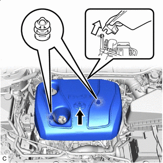

Engage the 2 hooks first 
Engage the 2 grommets next Engage the 2 hooks to the No. 2 engine cover bracket. Then align the 2 grommets with the 2 pins, and press down on the No. 1 engine cover to attach the pins.
-
-
INSTALL REAR ENGINE UNDER COVER LH
-
Install the rear engine under cover LH with the 5 clips.
-
-
INSTALL REAR ENGINE UNDER COVER RH
-
Install the rear engine under cover RH with the 5 clips.
-
-
INSTALL FRONT NO. 3 ENGINE UNDER COVER (for Full Cover Type)
-
Install the front No. 3 engine under cover with the 4 clips.
-
-
INSTALL CENTER NO. 4 ENGINE UNDER COVER (for Half Cover Type)
-
Install the center No. 4 engine under cover with the 5 clips.
-
-
INSTALL CENTER NO. 4 ENGINE UNDER COVER (for Full Cover Type)
-
Install the center No. 4 engine under cover with the 2 clips.
-
-
INSTALL NO. 1 ENGINE UNDER COVER (for Half Cover Type)
-
Install the No. 1 engine under cover with the 2 bolts and 7 clips.
-
-
INSTALL NO. 1 ENGINE UNDER COVER (for Full Cover Type)
-
Install the No. 1 engine under cover with the 2 bolts and 11 clips.
-
-
INSTALL FRONT LOWER BUMPER ABSORBER
-
Install the front lower bumper absorber with the 8 bolts and 4 screws.
-
-
INSTALL FRONT WHEELS
- Torque:
- 103 N*m { 1050 kgf*cm, 76 ft.*lbf }
-
ADJUST FRONT WHEEL ALIGNMENT
-
CHECK ABS SPEED SENSOR SIGNAL