METER / GAUGE SYSTEM Vehicle Speed Signal Circuit
DESCRIPTION
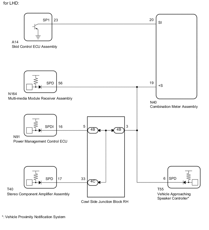
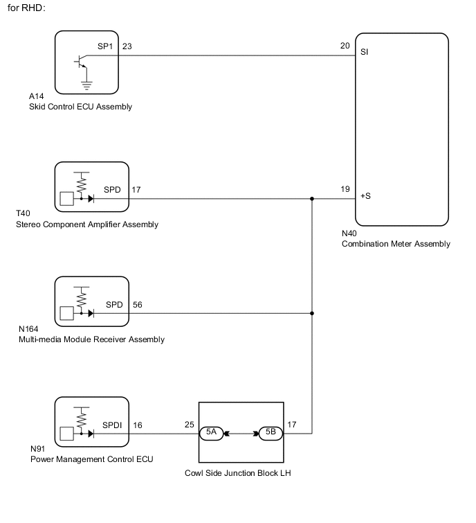
The vehicle speed signal consists of pulses sent to the combination meter assembly from the skid control ECU assembly.
WIRING DIAGRAM
PROCEDURE
-
CONFIRM MODEL
Result Result Proceed to for LHD A for RHD B
B 
CHECK STEREO COMPONENT AMPLIFIER ASSEMBLY Click here
A 
-
CHECK MULTI-MEDIA MODULE RECEIVER ASSEMBLY
-
*: w/ Vehicle Proximity Notification System
-
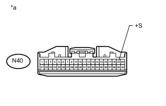
Text in Illustration *a Front view of wire harness connector
(to Combination Meter Assembly)
Disconnect the N40 combination meter assembly connector.
-
Disconnect the 4B junction block connector.
-
Disconnect the T55 vehicle approaching speaker controller connector.
-
Measure the voltage according to the value(s) in the table below.
Standard Voltage Tester Connection Switch Condition Specified Condition N40-19 (+S) - Body ground Power switch on (IG) 4.5 to 14 V Result Result Proceed to OK (w/ Vehicle Proximity Notification System) A OK (w/o Vehicle Proximity Notification System) B for RHD C
B
CHECK POWER MANAGEMENT CONTROL ECU Click here
C
CHECK HARNESS AND CONNECTOR (COMBINATION METER ASSEMBLY - MULTI-MEDIA MODULE RECEIVER ASSEMBLY) Click here
A
-
-
CHECK VEHICLE APPROACHING SPEAKER CONTROLLER
-
Text in Illustration *a Front view of wire harness connector
(to Combination Meter Assembly)
Disconnect the N40 combination meter assembly connector.
-
Disconnect the 4B junction block connector.
-
Disconnect the N164 multi-media module receiver assembly connector.
-
Measure the voltage according to the value(s) in the table below.
Standard Voltage Tester Connection Switch Condition Specified Condition N40-19 (+S) - Body ground Power switch on (IG) 4.5 to 14 V
NG
CHECK HARNESS AND CONNECTOR COMBINATION METER ASSEMBLY - VEHICLE APPROACHING SPEAKER CONTROLLER) Click here
OK
-
-
CHECK POWER MANAGEMENT CONTROL ECU
-
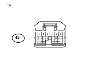
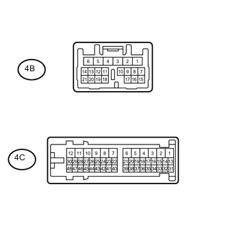
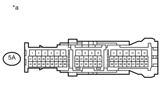
Text in Illustration *a Front view of wire harness connector
(to Cowl Side Junction Block RH)
Disconnect the 4B junction block connector.
-
Measure the voltage according to the value(s) in the table below.
Standard Voltage Tester Connection Switch Condition Specified Condition 4B-5 - Body ground Power switch on (IG) 4.5 to 14 V
NG
CHECK HARNESS AND CONNECTOR (COWL SIDE JUNCTION BLOCK RH - POWER MANAGEMENT CONTROL ECU) Click here
OK
-
-
CHECK STEREO COMPONENT AMPLIFIER ASSEMBLY
-
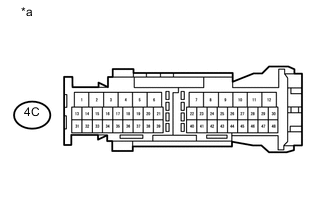
Text in Illustration *a Front view of wire harness connector
(to Cowl Side Junction Block RH)
Disconnect the 4C junction block connector.
-
Measure the voltage according to the value(s) in the table below.
Standard Voltage Tester Connection Switch Condition Specified Condition 4C-33 - Body ground Power switch on (IG) 4.5 to 14 V
NG
CHECK HARNESS AND CONNECTOR (COWL SIDE JUNCTION BLOCK RH - STEREO COMPONENT AMPLIFIER ASSEMBLY) Click here
OK
-
-
CHECK HARNESS AND CONNECTOR (COMBINATION METER ASSEMBLY - COWL SIDE JUNCTION BLOCK RH)
-
Disconnect the N40 combination meter assembly connector.
-
Disconnect the 4B junction block connector.
-
Disconnect the N164 multi-media module receiver assembly connector.
-
Measure the resistance according to the value(s) in the table below.
Standard Resistance Tester Connection Condition Specified Condition N40-19 (+S) - 4B-3 Always Below 1 Ω N40-19 (+S) - Body ground Always 10 kΩ or higher
NG 
REPAIR OR REPLACE HARNESS OR CONNECTOR
OK
-
-
INSPECT COWL SIDE JUNCTION BLOCK RH
-
Remove the cowl side junction block RH.
-
Measure the resistance according to the value(s) in the table below.
Standard Resistance Tester Connection Condition Specified Condition 4B-3 - 4B-5 Always Below 1 Ω 4B-3 - 4C-33
NG
REPLACE COWL SIDE JUNCTION BLOCK RH
OK
-
-
CHECK COMBINATION METER ASSEMBLY
-
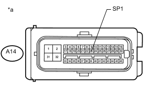
Text in Illustration *a Front view of wire harness connector
(to Skid Control ECU Assembly)
Disconnect the A14 skid control ECU assembly connector.
-
Measure the voltage according to the value(s) in the table below.
Standard Voltage Tester Connection Switch Condition Specified Condition A14-23 (SP1) - Body ground Power switch on (IG) 11 to 14 V
NG
CHECK HARNESS AND CONNECTOR (COMBINATION METER ASSEMBLY - SKID CONTROL ECU ASSEMBLY) Click here
OK
-
-
CHECK COMBINATION METER ASSEMBLY
-
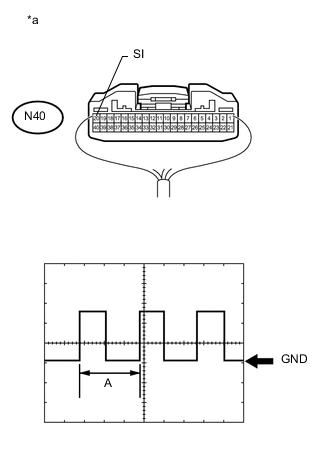
Text in Illustration *a Component with harness connected
(Combination Meter Assembly)
Remove the combination meter assembly with the connector(s) connected.
-
Connect an oscilloscope to terminal N40-20 (SI) and body ground.
-
Check the signal waveform according to the condition(s) in the table below.
Measurement Condition Item Condition Tester connection N40-20 (SI) - Body ground Tool setting 5 V/DIV., 20 ms/DIV. Vehicle condition Driving at approximately 20 km/h (12 mph) OK The waveform displayed is as shown in the illustration. Tech Tips
When the system is functioning normally, one wheel revolution generates 4 pulses. As the vehicle speed increases, the width indicated by (A) in the illustration narrows.
OK
REPLACE COMBINATION METER ASSEMBLY Click here
NG
REPLACE SKID CONTROL ECU ASSEMBLY Click here
-
-
CHECK HARNESS AND CONNECTOR (COMBINATION METER ASSEMBLY - MULTI-MEDIA MODULE RECEIVER ASSEMBLY)
-
Disconnect the N40 combination meter assembly connector.
-
Disconnect the N164 multi-media module receiver assembly connector.
-
Disconnect the 4B junction block connector.
-
Measure the resistance according to the value(s) in the table below.
Standard Resistance Tester Connection Condition Specified Condition N40-19 (+S) - N164-56 (SPD) Always Below 1 Ω N40-19 (+S) - Body ground Always 10 kΩ or higher
OK
REPLACE MULTI-MEDIA MODULE RECEIVER ASSEMBLY Click here
NG
REPAIR OR REPLACE HARNESS OR CONNECTOR
-
-
CHECK HARNESS AND CONNECTOR (COWL SIDE JUNCTION BLOCK RH - POWER MANAGEMENT CONTROL ECU)
-
Disconnect the 4B junction block connector.
-
Disconnect the N91 power management control ECU connector.
-
Measure the resistance according to the value(s) in the table below.
Standard Resistance Tester Connection Condition Specified Condition 4B-5 - N91-16 (SPDI) Always Below 1 Ω 4B-5 - Body ground Always 10 kΩ or higher
OK
REPLACE POWER MANAGEMENT CONTROL ECU Click here
NG
REPAIR OR REPLACE HARNESS OR CONNECTOR
-
-
CHECK HARNESS AND CONNECTOR (COWL SIDE JUNCTION BLOCK RH - STEREO COMPONENT AMPLIFIER ASSEMBLY)
-
Disconnect the 4C junction block connector.
-
Disconnect the T40 stereo component amplifier assembly connector.
-
Measure the resistance according to the value(s) in the table below.
Standard Resistance Tester Connection Condition Specified Condition 4C-33 - T40-17 (SPD) Always Below 1 Ω 4C-33 - Body ground Always 10 kΩ or higher
OK
REPLACE STEREO COMPONENT AMPLIFIER ASSEMBLY Click here
NG
REPAIR OR REPLACE HARNESS OR CONNECTOR
-
-
CHECK STEREO COMPONENT AMPLIFIER ASSEMBLY
-

Text in Illustration *a Front view of wire harness connector
(to Combination Meter Assembly)
Disconnect the N40 combination meter assembly connector.
-
Disconnect the N164 multi-media module receiver assembly connector.
-
Disconnect the 5B junction block connector.
-
Measure the voltage according to the value(s) in the table below.
Standard Voltage Tester Connection Switch Condition Specified Condition N40-19 (+S) - Body ground Power switch on (IG) 4.5 to 14 V
NG
CHECK HARNESS AND CONNECTOR (COMBINATION METER ASSEMBLY - STEREO COMPONENT AMPLIFIER ASSEMBLY) Click here
OK
-
-
CHECK MULTI-MEDIA MODULE RECEIVER ASSEMBLY
-
Text in Illustration *a Front view of wire harness connector
(to Combination Meter Assembly)
Disconnect the N40 combination meter assembly connector.
-
Disconnect the T40 stereo component amplifier assembly connector.
-
Disconnect the 5B junction block connector.
-
Measure the voltage according to the value(s) in the table below.
Standard Voltage Tester Connection Switch Condition Specified Condition N40-19 (+S) - Body ground Power switch on (IG) 4.5 to 14 V
NG
CHECK HARNESS AND CONNECTOR (COMBINATION METER ASSEMBLY - MULTI-MEDIA MODULE RECEIVER ASSEMBLY) Click here
OK
-
-
CHECK POWER MANAGEMENT CONTROL ECU
-
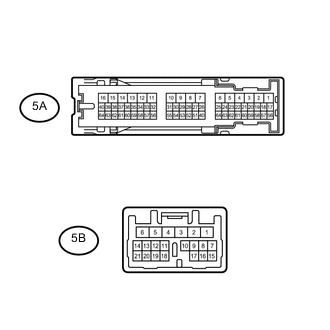
Text in Illustration *a Front view of wire harness connector
(to Cowl Side Junction Block LH)
Disconnect the 5A junction block connector.
-
Measure the voltage according to the value(s) in the table below.
Standard Voltage Tester Connection Switch Condition Specified Condition 5A-25 - Body ground Power switch on (IG) 4.5 to 14 V
NG
CHECK HARNESS AND CONNECTOR (COWL SIDE JUNCTION BLOCK LH - POWER MANAGEMENT CONTROL ECU) Click here
OK
-
-
CHECK HARNESS AND CONNECTOR (COMBINATION METER ASSEMBLY - COWL SIDE JUNCTION BLOCK LH)
-
Disconnect the N40 combination meter assembly connector.
-
Disconnect the 5B junction block connector.
-
Disconnect the T40 stereo component amplifier assembly connector.
-
Disconnect the N164 multi-media module receiver assembly connector.
-
Measure the resistance according to the value(s) in the table below.
Standard Resistance Tester Connection Condition Specified Condition N40-19 (+S) - 5B-17 Always Below 1 Ω N40-19 (+S) - Body ground Always 10 kΩ or higher
NG
REPAIR OR REPLACE HARNESS OR CONNECTOR
OK
-
-
INSPECT COWL SIDE JUNCTION BLOCK LH
-
Remove the cowl side junction block LH Click here.
-
Measure the resistance according to the value(s) in the table below.
Standard Resistance Tester Connection Condition Specified Condition 5B-17 - 5A-25 Always Below 1 Ω
NG
REPLACE COWL SIDE JUNCTION BLOCK LH Click here
OK
-
-
CHECK COMBINATION METER ASSEMBLY
-
Text in Illustration *a Front view of wire harness connector
(to Skid Control ECU Assembly)
Disconnect the A14 skid control ECU assembly connector.
-
Measure the voltage according to the value(s) in the table below.
Standard Voltage Tester Connection Switch Condition Specified Condition A14-23 (SP1) - Body ground Power switch on (IG) 11 to 14 V
NG
CHECK HARNESS AND CONNECTOR (COMBINATION METER ASSEMBLY - SKID CONTROL ECU ASSEMBLY) Click here
OK
-
-
CHECK COMBINATION METER ASSEMBLY
-
Text in Illustration *a Component with harness connected
(Combination Meter Assembly)
Remove the combination meter assembly with the connector(s) connected.
-
Connect an oscilloscope to terminal N40-20 (SI) and body ground.
-
Check the signal waveform according to the condition(s) in the table below.
Measurement Condition Item Condition Tester connection N40-20 (SI) - Body ground Tool setting 5 V/DIV., 20 ms/DIV. Vehicle condition Driving at approximately 20 km/h (12 mph) OK The waveform displayed is as shown in the illustration. Tech Tips
When the system is functioning normally, one wheel revolution generates 4 pulses. As the vehicle speed increases, the width indicated by (A) in the illustration narrows.
OK
REPLACE COMBINATION METER ASSEMBLY Click here
NG
REPLACE SKID CONTROL ECU ASSEMBLY Click here
-
-
CHECK HARNESS AND CONNECTOR (COMBINATION METER ASSEMBLY - STEREO COMPONENT AMPLIFIER ASSEMBLY)
-
Disconnect the N40 combination meter assembly connector.
-
Disconnect the T40 stereo component amplifier assembly connector.
-
Disconnect the N164 multi-media module receiver assembly connector.
-
Disconnect the 5B junction block connector.
-
Measure the resistance according to the value(s) in the table below.
Standard Resistance Tester Connection Condition Specified Condition N40-19 (+S) - T40-17 (SPD) Always Below 1 Ω N40-19 (+S) - Body ground Always 10 kΩ or higher
OK
REPLACE STEREO COMPONENT AMPLIFIER ASSEMBLY Click here
NG
REPAIR OR REPLACE HARNESS OR CONNECTOR
-
-
CHECK HARNESS AND CONNECTOR (COMBINATION METER ASSEMBLY - MULTI-MEDIA MODULE RECEIVER ASSEMBLY)
-
Disconnect the N40 combination meter assembly connector.
-
Disconnect the N164 multi-media module receiver assembly connector.
-
Disconnect the T40 stereo component amplifier assembly connector.
-
Disconnect the 5B junction block connector.
-
Measure the resistance according to the value(s) in the table below.
Standard Resistance Tester Connection Condition Specified Condition N40-19 (+S) - N164-56 (SPD) Always Below 1 Ω N40-19 (+S) - Body ground Always 10 kΩ or higher
OK
REPLACE MULTI-MEDIA MODULE RECEIVER ASSEMBLY Click here
NG
REPAIR OR REPLACE HARNESS OR CONNECTOR
-
-
CHECK HARNESS AND CONNECTOR (COWL SIDE JUNCTION BLOCK LH - POWER MANAGEMENT CONTROL ECU)
-
Disconnect the 5A junction block connector.
-
Disconnect the N91 power management control ECU connector.
-
Measure the resistance according to the value(s) in the table below.
Standard Resistance Tester Connection Condition Specified Condition 5A-25 - N91-16 (SPDI) Always Below 1 Ω 5A-25 - Body ground Always 10 kΩ or higher
OK
REPLACE POWER MANAGEMENT CONTROL ECU Click here
NG
REPAIR OR REPLACE HARNESS OR CONNECTOR
-
-
CHECK HARNESS AND CONNECTOR (COMBINATION METER ASSEMBLY - SKID CONTROL ECU ASSEMBLY)
-
Disconnect the N40 combination meter assembly connector.
-
Disconnect the A14 skid control ECU assembly connector.
-
Measure the resistance according to the value(s) in the table below.
Standard Resistance Tester Connection Condition Specified Condition N40-20 (SI) - A14-23 (SP1) Always Below 1 Ω N40-20 (SI) - Body ground Always 10 kΩ or higher
OK
REPLACE COMBINATION METER ASSEMBLY Click here
NG
REPAIR OR REPLACE HARNESS OR CONNECTOR
-
-
CHECK HARNESS AND CONNECTOR COMBINATION METER ASSEMBLY - VEHICLE APPROACHING SPEAKER CONTROLLER)
-
Disconnect the N40 combination meter assembly connector.
-
Disconnect the 4B junction block connector.
-
Disconnect the N164 multi-media module receiver assembly connector.
-
Disconnect the T55 vehicle approaching speaker controller connector.
-
Measure the resistance according to the value(s) in the table below.
Standard Resistance Tester Connection Condition Specified Condition N40-19 (+S) - T55-6 (SPD) Always Below 1 Ω N40-19 (+S) - Body ground Always 10 kΩ or higher
OK
REPLACE VEHICLE APPROACHING SPEAKER CONTROLLER Click here
NG
REPAIR OR REPLACE HARNESS OR CONNECTOR
-