LIN COMMUNICATION SYSTEM, Diagnostic DTC:B2325
| DTC Code | DTC Name |
|---|---|
| B2325 | LIN Communication Bus Malfunction |
DESCRIPTION
The main body ECU (multiplex network body ECU) monitors the LIN communication bus between the components related to the door and sliding roof intermittently. DTC B2325 is output when a malfunction in the LIN communication bus between the components related to the door and sliding roof is detected continuously 3 times.
| DTC Code | DTC Detection Condition | Trouble Area |
|---|---|---|
| B2325 | Main body ECU (multiplex network body ECU) detects malfunction of LIN communication bus between components related to door and sliding roof continuously 3 times |
|
-
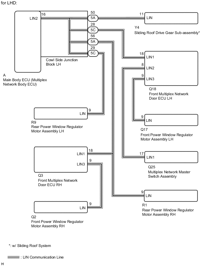
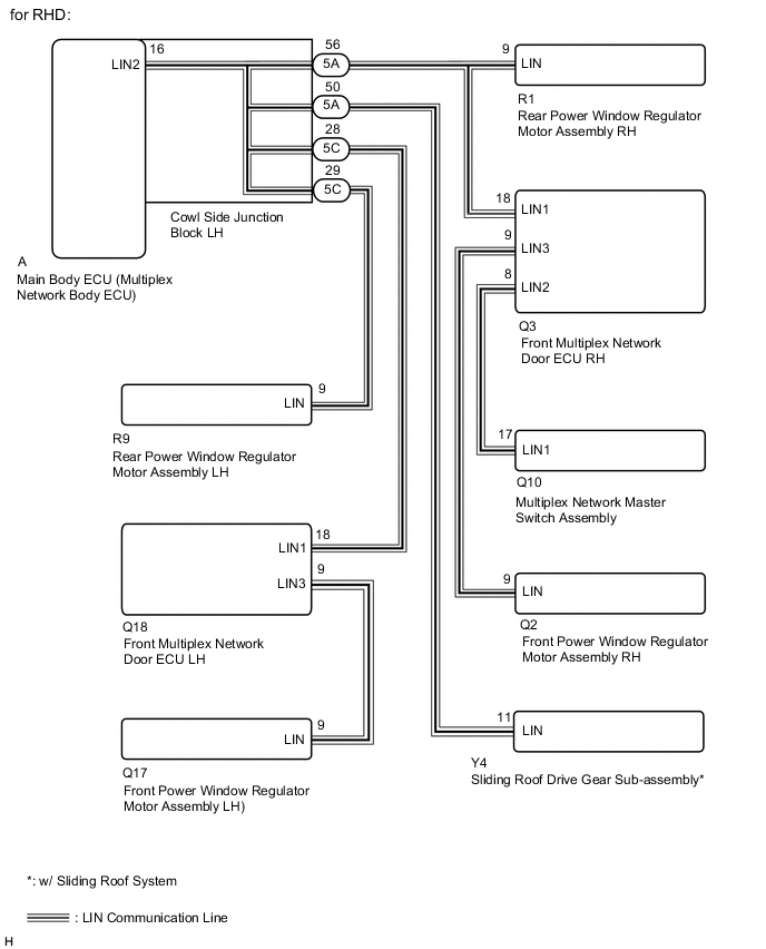
*: w/ Sliding Roof System
WIRING DIAGRAM
CAUTION / NOTICE / HINT
Note
-
When using the GTS with the power switch off to troubleshoot:
Connect the GTS to the vehicle, and turn a courtesy switch on and off at 1.5 seconds intervals until communication between the GTS and vehicle begins.
-
When the sliding roof drive gear sub-assembly is replaced or removed and reinstalled, it requires initialization Click here.*
-
When a power window regulator motor assembly is replaced or removed and reinstalled, it requires initialization Click here.
-
If the main body ECU (multiplex network body ECU) is replaced, refer to the Service Bulletin.
-
*: w/ Sliding Roof System
Tech Tips
When DTC B2325 and a LIN communication stop DTC are output simultaneously, first perform the troubleshooting for the LIN communication stop DTC. Then perform the troubleshooting for DTC B2325.
PROCEDURE
-
CLEAR DTC
-
Clear the DTCs Click here.
NEXT 
-
-
CHECK FOR DTC
-
Check for DTCs Click here.
Result Result Proceed to DTC B2325 is output A DTC B2325 is not output B
B 
USE SIMULATION METHOD TO CHECK Click here
A
-
-
CHECK VEHICLE TYPE
-
Cheek vehicle type.
Result Result Proceed to for LHD A for RHD B
B 
CHECK HARNESS AND CONNECTOR (MAIN BODY ECU [MULTIPLEX NETWORK BODY ECU] - MULTIPLEX NETWORK MASTER SWITCH ASSEMBLY) Click here
A
-
-
CHECK HARNESS AND CONNECTOR (MAIN BODY ECU [MULTIPLEX NETWORK BODY ECU] - MULTIPLEX NETWORK MASTER SWITCH ASSEMBLY)
-
Remove the main body ECU (multiplex network body ECU) from the cowl side junction block LH Click here.
-
Disconnect the Q25 multiplex network master switch assembly connector.
-
Measure the resistance according to the value(s) in the table below.
Standard Resistance Tester Connection Condition Specified Condition A-16 (LIN2) - Q25-17 (LIN1) Always Below 1 Ω Q25-17 (LIN1) - Body ground Always 10 kΩ or higher
NG
CHECK HARNESS AND CONNECTOR (COWL SIDE JUNCTION BLOCK LH - MULTIPLEX NETWORK MASTER SWITCH ASSEMBLY) Click here
OK
-
-
CHECK HARNESS AND CONNECTOR (MAIN BODY ECU [MULTIPLEX NETWORK BODY ECU] - FRONT POWER WINDOW REGULATOR MOTOR ASSEMBLY LH)
-
Remove the main body ECU (multiplex network body ECU) from the cowl side junction block LH Click here.
-
Disconnect the Q17 front power window regulator motor assembly LH connector.
-
Measure the resistance according to the value(s) in the table below.
Standard Resistance Tester Connection Condition Specified Condition A-16 (LIN2) - Q17-9 (LIN) Always Below 1 Ω Q17-9 (LIN) - Body ground Always 10 kΩ or higher
NG
CHECK HARNESS AND CONNECTOR (COWL SIDE JUNCTION BLOCK LH - FRONT POWER WINDOW REGULATOR MOTOR ASSEMBLY LH) Click here
OK
-
-
CHECK HARNESS AND CONNECTOR (MAIN BODY ECU [MULTIPLEX NETWORK BODY ECU] - REAR POWER WINDOW REGULATOR MOTOR ASSEMBLY RH)
-
Remove the main body ECU (multiplex network body ECU) from the cowl side junction block LH Click here.
-
Disconnect the R1 rear power window regulator motor assembly RH connector.
-
Measure the resistance according to the value(s) in the table below.
Standard Resistance Tester Connection Condition Specified Condition A-16 (LIN2) - R1-9 (LIN) Always Below 1 Ω R1-9 (LIN) - Body ground Always 10 kΩ or higher
NG
CHECK HARNESS AND CONNECTOR (COWL SIDE JUNCTION BLOCK LH - REAR POWER WINDOW REGULATOR MOTOR ASSEMBLY RH) Click here
OK
-
-
CHECK HARNESS AND CONNECTOR (MAIN BODY ECU [MULTIPLEX NETWORK BODY ECU] - FRONT POWER WINDOW REGULATOR MOTOR ASSEMBLY RH)
-
Remove the main body ECU (multiplex network body ECU) from the cowl side junction block LH Click here.
-
Disconnect the Q2 front power window regulator motor assembly RH connector.
-
Measure the resistance according to the value(s) in the table below.
Standard Resistance Tester Connection Condition Specified Condition A-16 (LIN2) - Q2-9 (LIN) Always Below 1 Ω Q2-9 (LIN) - Body ground Always 10 kΩ or higher
NG
CHECK HARNESS AND CONNECTOR (COWL SIDE JUNCTION BLOCK LH - FRONT POWER WINDOW REGULATOR MOTOR ASSEMBLY RH) Click here
OK
-
-
CHECK HARNESS AND CONNECTOR (MAIN BODY ECU [MULTIPLEX NETWORK BODY ECU] - REAR POWER WINDOW REGULATOR MOTOR ASSEMBLY LH)
-
Remove the main body ECU (multiplex network body ECU) from the cowl side junction block LH Click here.
-
Disconnect the R9 rear power window regulator motor assembly LH connector.
Standard Resistance Tester Connection Condition Specified Condition A-16 (LIN2) - R9-9 (LIN) Always Below 1 Ω R9-9 (LIN) - Body ground Always 10 kΩ or higher Result Result Proceed to OK (w/ Sliding Roof System) A OK (w/o Sliding Roof System) B NG C
B
CLEAR DTC Click here
C
CHECK HARNESS AND CONNECTOR (COWL SIDE JUNCTION BLOCK LH - REAR POWER WINDOW REGULATOR MOTOR ASSEMBLY LH) Click here
A
-
-
CHECK HARNESS AND CONNECTOR (MAIN BODY ECU [MULTIPLEX NETWORK BODY ECU] - SLIDING ROOF DRIVE GEAR ASSEMBLY)
-
Remove the main body ECU (multiplex network body ECU) from the cowl side junction block LH Click here.
-
Disconnect the Y4 sliding roof drive gear sub-assembly connector.
-
Measure the resistance according to the value(s) in the table below.
Standard Resistance Tester Connection Condition Specified Condition A-16 (LIN2) - Y4-11 (LIN) Always Below 1 Ω Y4-11 (LIN) - Body ground Always 10 kΩ or higher
NG
CHECK HARNESS AND CONNECTOR (COWL SIDE JUNCTION BLOCK LH - SLIDING ROOF DRIVE GEAR SUB-ASSEMBLY) Click here
OK
-
-
CLEAR DTC
-
Clear the DTCs Click here.
NEXT
-
-
CHECK FOR DTC
-
Disconnect the Q25 multiplex network master switch assembly connector.
-
Check for DTCs Click here.
Result Result Proceed to DTC B2325 is output A DTC B2325 is not output B
B
REPLACE MULTIPLEX NETWORK MASTER SWITCH ASSEMBLY Click here
A
-
-
CLEAR DTC
-
Clear the DTCs Click here.
NEXT
-
-
CHECK FOR DTC
-
Disconnect the Q17 front power window regulator motor assembly LH connector.
-
Check for DTCs Click here.
Result Result Proceed to DTC B2325 is output A DTC B2325 is not output B
B
REPLACE FRONT POWER WINDOW REGULATOR MOTOR ASSEMBLY LH Click here
A
-
-
CLEAR DTC
-
Clear the DTCs Click here.
NEXT
-
-
CHECK FOR DTC
-
Disconnect the Q2 front power window regulator motor assembly RH connector.
-
Check for DTCs Click here.
Result Result Proceed to DTC B2325 is output A DTC B2325 is not output B
B
REPLACE FRONT POWER WINDOW REGULATOR MOTOR ASSEMBLY RH Click here
A
-
-
CLEAR DTC
-
Clear the DTCs Click here.
NEXT
-
-
CHECK FOR DTC
-
Disconnect the R1 rear power window regulator motor assembly RH connector.
-
Check for DTCs Click here.
Result Result Proceed to DTC B2325 is output A DTC B2325 is not output B
B
REPLACE REAR POWER WINDOW REGULATOR MOTOR ASSEMBLY RH Click here
A
-
-
CLEAR DTC
-
Clear the DTCs Click here.
NEXT
-
-
CHECK FOR DTC
-
Disconnect the R9 rear power window regulator motor assembly LH connector.
-
Recheck for DTC Click here.
Result Result Proceed to DTC B2325 is output (w/ Sliding roof system) A DTC B2325 is output (w/o Sliding roof system) B DTC B2325 is not output C
B
REPLACE MAIN BODY ECU (MULTIPLEX NETWORK BODY ECU) Click here
C
REPLACE REAR POWER WINDOW REGULATOR MOTOR ASSEMBLY LH Click here
A
-
-
CLEAR DTC
-
Clear the DTCs Click here.
NEXT
-
-
CHECK FOR DTC
-
Disconnect the Y4 sliding roof drive gear sub-assembly connector.
-
Check for DTCs Click here.
Result Result Proceed to DTC B2325 is output A DTC B2325 is not output B
A
REPLACE MAIN BODY ECU (MULTIPLEX NETWORK BODY ECU) Click here
B
REPLACE SLIDING ROOF DRIVE GEAR SUB-ASSEMBLY Click here
-
-
CHECK HARNESS AND CONNECTOR (COWL SIDE JUNCTION BLOCK LH - MULTIPLEX NETWORK MASTER SWITCH ASSEMBLY)
-
Disconnect the 5C cowl side junction block LH connector.
-
Disconnect the Q25 multiplex network master switch assembly connector.
-
Measure the resistance according to the value(s) in the table below.
Standard Resistance Tester Connection Condition Specified Condition 5C-28 - Q25-17 (LIN1) Always Below 1 Ω Q25-17 (LIN1) - Body ground Always 10 kΩ or higher
OK
REPLACE COWL SIDE JUNCTION BLOCK LH Click here
NG
-
-
CHECK HARNESS AND CONNECTOR (FRONT MULTIPLEX NETWORK DOOR ECU LH - COWL SIDE JUNCTION BLOCK LH OR MULTIPLEX NETWORK MASTER SWITCH ASSEMBLY)
-
Disconnect the Q18 front multiplex network door ECU LH connector.
-
Disconnect the 5C cowl side junction block LH connector.
-
Disconnect the Q25 multiplex network master switch assembly connector.
-
Measure the resistance according to the value(s) in the table below.
Standard Resistance Tester Connection Condition Specified Condition Q18-18 (LIN1) - 5C-28 Always Below 1 Ω Q18-8 (LIN2) - Q25-17 (LIN1) Always Below 1 Ω Q18-18 (LIN1) - Body ground Always 10 kΩ or higher Q18-8 (LIN2) - Body ground Always 10 kΩ or higher
OK
REPLACE FRONT MULTIPLEX NETWORK DOOR ECU LH Click here
NG
REPAIR OR REPLACE HARNESS OR CONNECTOR
-
-
CHECK HARNESS AND CONNECTOR (COWL SIDE JUNCTION BLOCK LH - FRONT POWER WINDOW REGULATOR MOTOR ASSEMBLY LH)
-
Disconnect the 5C cowl side junction block LH connector.
-
Disconnect the Q17 front power window regulator motor assembly LH connector.
-
Measure the resistance according to the value(s) in the table below.
Standard Resistance Tester Connection Condition Specified Condition 5C-28 - Q17-9 (LIN) Always Below 1 Ω Q17-9 (LIN) - Body ground Always 10 kΩ or higher
OK
REPLACE COWL SIDE JUNCTION BLOCK LH Click here
NG
-
-
CHECK HARNESS AND CONNECTOR (FRONT MULTIPLEX NETWORK DOOR ECU LH - COWL SIDE JUNCTION BLOCK LH OR FRONT POWER WINDOW REGULATOR MOTOR ASSEMBLY LH)
-
Disconnect the Q18 front multiplex network door ECU LH connector.
-
Disconnect the 5C cowl side junction block LH connector.
-
Disconnect the Q17 front power window regulator motor assembly LH connector.
-
Measure the resistance according to the value(s) in the table below.
Standard Resistance Tester Connection Condition Specified Condition 5C-28 -
Q18-18 (LIN1)
Always Below 1 Ω Q18-9 (LIN3) - Q17-9 (LIN) Always Below 1 Ω Q18-18 (LIN1) - Body ground Always 10 kΩ or higher Q17-9 (LIN) - Body ground Always 10 kΩ or higher
OK
REPLACE FRONT MULTIPLEX NETWORK DOOR ECU LH Click here
NG
REPAIR OR REPLACE HARNESS OR CONNECTOR
-
-
CHECK HARNESS AND CONNECTOR (COWL SIDE JUNCTION BLOCK LH - REAR POWER WINDOW REGULATOR MOTOR ASSEMBLY RH)
-
Disconnect the 5A cowl side junction block LH connector.
-
Disconnect the R1 rear power window regulator motor assembly RH connector.
-
Measure the resistance according to the value(s) in the table below.
Standard Resistance Tester Connection Condition Specified Condition 5A-56 - R1-9 (LIN) Always Below 1 Ω R1-9 (LIN) - Body ground Always 10 kΩ or higher
OK
REPLACE COWL SIDE JUNCTION BLOCK LH Click here
NG
REPAIR OR REPLACE HARNESS OR CONNECTOR
-
-
CHECK HARNESS AND CONNECTOR (COWL SIDE JUNCTION BLOCK LH - FRONT POWER WINDOW REGULATOR MOTOR ASSEMBLY RH)
-
Disconnect the 5A cowl side junction block LH connector.
-
Disconnect the Q2 front power window regulator motor assembly RH connector.
-
Measure the resistance according to the value(s) in the table below.
Standard Resistance Tester Connection Condition Specified Condition 5A-56 - Q2-9 (LIN) Always Below 1 Ω Q2-9 (LIN) - Body ground Always 10 kΩ or higher
OK
REPLACE COWL SIDE JUNCTION BLOCK LH Click here
NG
-
-
CHECK HARNESS AND CONNECTOR (FRONT MULTIPLEX NETWORK DOOR ECU RH - COWL SIDE JUNCTION BLOCK LH OR FRONT POWER WINDOW REGULATOR MOTOR ASSEMBLY RH)
-
Disconnect the Q3 front multiplex network door ECU RH connector.
-
Disconnect the 5A cowl side junction block LH connector.
-
Disconnect the Q2 front power window regulator motor assembly RH connector.
-
Measure the resistance according to the value(s) in the table below.
Standard Resistance Tester Connection Condition Specified Condition Q3-18 (LIN1) - 5A-56 Always Below 1 Ω Q3-9 (LIN3) - Q2-9 (LIN) Always Below 1 Ω Q3-18 (LIN1) - Body ground Always 10 kΩ or higher Q2-9 (LIN) - Body ground Always 10 kΩ or higher
OK
REPLACE FRONT MULTIPLEX NETWORK DOOR ECU LH Click here
NG
REPAIR OR REPLACE HARNESS OR CONNECTOR
-
-
CHECK HARNESS AND CONNECTOR (COWL SIDE JUNCTION BLOCK LH - REAR POWER WINDOW REGULATOR MOTOR ASSEMBLY LH)
-
Disconnect the 5C cowl side junction block LH connector.
-
Disconnect the R9 rear power window regulator motor assembly LH connector.
-
Measure the resistance according to the value(s) in the table below.
Standard Resistance Tester Connection Condition Specified Condition 5C-29 - R9-9 (LIN) Always Below 1 Ω R9-9 (LIN) - Body ground Always 10 kΩ or higher
OK
REPLACE COWL SIDE JUNCTION BLOCK LH Click here
NG
REPAIR OR REPLACE HARNESS OR CONNECTOR
-
-
CHECK HARNESS AND CONNECTOR (COWL SIDE JUNCTION BLOCK LH - SLIDING ROOF DRIVE GEAR SUB-ASSEMBLY)
-
Disconnect the 5A cowl side junction block LH connector.
-
Disconnect the Y4 sliding roof drive gear sub-assembly connector.
-
Measure the resistance according to the value(s) in the table below.
Standard Resistance Tester Connection Condition Specified Condition 5A-50 - Y4-11 (LIN) Always Below 1 Ω Y4-11 (LIN) - Body ground Always 10 kΩ or higher
OK
REPLACE COWL SIDE JUNCTION BLOCK LH Click here
NG
REPAIR OR REPLACE HARNESS OR CONNECTOR
-
-
CHECK HARNESS AND CONNECTOR (MAIN BODY ECU [MULTIPLEX NETWORK BODY ECU] - MULTIPLEX NETWORK MASTER SWITCH ASSEMBLY)
-
Remove the main body ECU (multiplex network body ECU) from the cowl side junction block LH Click here.
-
Disconnect the Q10 multiplex network master switch assembly connector.
-
Measure the resistance according to the value(s) in the table below.
Standard Resistance Tester Connection Condition Specified Condition A-16 (LIN2) - Q10-17 (LIN1) Always Below 1 Ω Q10-17 (LIN1) - Body ground Always 10 kΩ or higher
NG
CHECK HARNESS AND CONNECTOR (COWL SIDE JUNCTION BLOCK LH - MULTIPLEX NETWORK MASTER SWITCH ASSEMBLY) Click here
OK
-
-
CHECK HARNESS AND CONNECTOR (MAIN BODY ECU [MULTIPLEX NETWORK BODY ECU] - FRONT POWER WINDOW REGULATOR MOTOR ASSEMBLY RH)
-
Remove the main body ECU (multiplex network body ECU) from the cowl side junction block LH Click here.
-
Disconnect the Q2 front power window regulator motor assembly RH connector.
-
Measure the resistance according to the value(s) in the table below.
Standard Resistance Tester Connection Condition Specified Condition A-16 (LIN2) - Q2-9 (LIN) Always Below 1 Ω Q2-9 (LIN) - Body ground Always 10 kΩ or higher
NG
CHECK HARNESS AND CONNECTOR (COWL SIDE JUNCTION BLOCK LH - FRONT POWER WINDOW REGULATOR MOTOR ASSEMBLY RH) Click here
OK
-
-
CHECK HARNESS AND CONNECTOR (MAIN BODY ECU [MULTIPLEX NETWORK BODY ECU] - REAR POWER WINDOW REGULATOR MOTOR ASSEMBLY RH)
-
Remove the main body ECU (multiplex network body ECU) from the cowl side junction block LH Click here.
-
Disconnect the R1 rear power window regulator motor assembly RH connector.
-
Measure the resistance according to the value(s) in the table below.
Standard Resistance Tester Connection Condition Specified Condition A-16 (LIN2) - R1-9 (LIN) Always Below 1 Ω R1-9 (LIN) - Body ground Always 10 kΩ or higher
NG
CHECK HARNESS AND CONNECTOR (COWL SIDE JUNCTION BLOCK LH - REAR POWER WINDOW REGULATOR MOTOR ASSEMBLY RH) Click here
OK
-
-
CHECK HARNESS AND CONNECTOR (MAIN BODY ECU [MULTIPLEX NETWORK BODY ECU] - FRONT POWER WINDOW REGULATOR MOTOR ASSEMBLY LH)
-
Remove the main body ECU (multiplex network body ECU) from the cowl side junction block LH Click here.
-
Disconnect the Q17 front power window regulator motor assembly LH connector.
-
Measure the resistance according to the value(s) in the table below.
Standard Resistance Tester Connection Condition Specified Condition A-16 (LIN2) - Q17-9 (LIN) Always Below 1 Ω R17-9 (LIN) - Body ground Always 10 kΩ or higher
NG
CHECK HARNESS AND CONNECTOR (COWL SIDE JUNCTION BLOCK LH - FRONT POWER WINDOW REGULATOR MOTOR ASSEMBLY LH) Click here
OK
-
-
CHECK HARNESS AND CONNECTOR (MAIN BODY ECU [MULTIPLEX NETWORK BODY ECU] - REAR POWER WINDOW REGULATOR MOTOR ASSEMBLY LH)
-
Remove the main body ECU (multiplex network body ECU) from the cowl side junction block LH Click here.
-
Disconnect the R9 rear power window regulator motor assembly LH connector.
-
Measure the resistance according to the value(s) in the table below.
Standard Resistance Tester Connection Condition Specified Condition A-16 (LIN2) - R9-9 (LIN) Always Below 1 Ω R9-9 (LIN) - Body ground Always 10 kΩ or higher Result Result Proceed to OK (w/ Sliding Roof System) A OK (w/o Sliding Roof System) B NG C
B
CLEAR DTC Click here
C
CHECK HARNESS AND CONNECTOR (COWL SIDE JUNCTION BLOCK LH - REAR POWER WINDOW REGULATOR MOTOR ASSEMBLY LH) Click here
A
-
-
CHECK HARNESS AND CONNECTOR (MAIN BODY ECU [MULTIPLEX NETWORK BODY ECU] - SLIDING ROOF DRIVE GEAR ASSEMBLY)
-
Remove the main body ECU (multiplex network body ECU) from the cowl side junction block LH Click here.
-
Disconnect the Y4 sliding roof drive gear assembly connector.
-
Measure the resistance according to the value(s) in the table below.
Standard Resistance Tester Connection Condition Specified Condition A-16 (LIN2) - Y4-11 (LIN) Always Below 1 Ω Y4-11 (LIN) - Body ground Always 10 kΩ or higher
NG
CHECK HARNESS AND CONNECTOR (COWL SIDE JUNCTION BLOCK LH - SLIDING ROOF DRIVE GEAR ASSEMBLY) Click here
OK
-
-
CLEAR DTC
-
Clear the DTCs Click here.
NEXT
-
-
CHECK FOR DTC
-
Disconnect the Q10 multiplex network master switch assembly connector.
-
Check for DTCs Click here.
Result Result Proceed to DTC B2325 is output A DTC B2325 is not output B
B
REPLACE MULTIPLEX NETWORK MASTER SWITCH ASSEMBLY Click here
A
-
-
CLEAR DTC
-
Clear the DTCs Click here.
NEXT
-
-
CHECK FOR DTC
-
Disconnect the Q2 front power window regulator motor assembly RH connector.
-
Check for DTCs Click here.
Result Result Proceed to DTC B2325 is output A DTC B2325 is not output B
B
REPLACE FRONT POWER WINDOW REGULATOR MOTOR ASSEMBLY RH Click here
A
-
-
CLEAR DTC
-
Clear the DTCs Click here.
NEXT
-
-
CHECK FOR DTC
-
Disconnect the Q17 front power window regulator motor assembly LH connector.
-
Check for DTCs Click here.
Result Result Proceed to DTC B2325 is output A DTC B2325 is not output B
B
REPLACE FRONT POWER WINDOW REGULATOR MOTOR ASSEMBLY LH Click here
A
-
-
CLEAR DTC
-
Clear the DTCs Click here.
NEXT
-
-
CHECK FOR DTC
-
Disconnect the R1 rear power window regulator motor assembly RH connector.
-
Check for DTCs Click here.
Result Result Proceed to DTC B2325 is output A DTC B2325 is not output B
B
REPLACE REAR POWER WINDOW REGULATOR MOTOR ASSEMBLY RH Click here
A
-
-
CLEAR DTC
-
Clear the DTCs Click here.
NEXT
-
-
CHECK FOR DTC
-
Disconnect the R9 rear power window regulator motor assembly LH connector.
-
Check for DTCs Click here.
Result Result Proceed to DTC B2325 is output (w/ Sliding Roof System) A DTC B2325 is output (w/o Sliding Roof System) B DTC B2325 is not output C
B
REPLACE MAIN BODY ECU (MULTIPLEX NETWORK BODY ECU) Click here
C
REPLACE REAR POWER WINDOW REGULATOR MOTOR ASSEMBLY LH Click here
A
-
-
CLEAR DTC
-
Clear the DTCs Click here.
NEXT
-
-
CHECK FOR DTC
-
Disconnect the Y4 sliding roof drive gear sub-assembly connector.
-
Check for DTCs Click here.
Result Result Proceed to DTC B2325 is output A DTC B2325 is not output B
A
REPLACE MAIN BODY ECU (MULTIPLEX NETWORK BODY ECU) Click here
B
REPLACE SLIDING ROOF DRIVE GEAR SUB-ASSEMBLY Click here
-
-
CHECK HARNESS AND CONNECTOR (COWL SIDE JUNCTION BLOCK LH - MULTIPLEX NETWORK MASTER SWITCH ASSEMBLY)
-
Disconnect the 5A cowl side junction block LH .
-
Disconnect the Q10 multiplex network master switch assembly connector.
-
Measure the resistance according to the value(s) in the table below.
Standard Resistance Tester Connection Condition Specified Condition 5A-56 - Q10-17 (LIN1) Always Below 1 Ω Q10-17 (LIN1) - Body ground Always 10 kΩ or higher
OK
REPLACE COWL SIDE JUNCTION BLOCK LH Click here
NG
-
-
CHECK HARNESS AND CONNECTOR (FRONT MULTIPLEX NETWORK DOOR ECU RH - COWL SIDE JUNCTION BLOCK LH AND MULTIPLEX NETWORK MASTER SWITCH ASSEMBLY)
-
Disconnect the Q3 front multiplex network door ECU RH connector.
-
Disconnect the 5A cowl side junction block LH connector.
-
Disconnect the Q10 multiplex network master switch assembly connector.
-
Measure the resistance according to the value(s) in the table below.
Standard Resistance Tester Connection Condition Specified Condition Q3-18 (LIN1) - 5A-56 Always Below 1 Ω Q3-8 (LIN2) - Q10-17 (LIN1) Always Below 1 Ω Q3-18 (LIN1) - Body ground Always 10 kΩ or higher Q3-8 (LIN2) - Body ground Always 10 kΩ or higher
OK
REPLACE FRONT MULTIPLEX NETWORK DOOR ECU LH Click here
NG
REPAIR OR REPLACE HARNESS OR CONNECTOR
-
-
CHECK HARNESS AND CONNECTOR (COWL SIDE JUNCTION BLOCK LH - FRONT POWER WINDOW REGULATOR MOTOR ASSEMBLY RH)
-
Disconnect the 5A cowl side junction block LH.
-
Disconnect the Q2 front power window regulator motor assembly RH connector.
-
Measure the resistance according to the value(s) in the table below.
Standard Resistance Tester Connection Condition Specified Condition 5A-56 - Q2-9 (LIN) Always Below 1 Ω Q2-9 (LIN) - Body ground Always 10 kΩ or higher
OK
REPLACE COWL SIDE JUNCTION BLOCK LH Click here
NG
-
-
CHECK HARNESS AND CONNECTOR (FRONT MULTIPLEX NETWORK DOOR ECU RH - COWL SIDE JUNCTION BLOCK LH AND FRONT POWER WINDOW REGULATOR MOTOR ASSEMBLY RH)
-
Disconnect the Q3 front multiplex network door ECU LH connector.
-
Disconnect the 5A cowl side junction block LH connector.
-
Disconnect the Q2 front power window regulator motor assembly RH connector.
-
Measure the resistance according to the value(s) in the table below.
Standard Resistance Tester Connection Condition Specified Condition 5A-56 - Q3-18 (LIN1) Always Below 1 Ω Q3-9 (LIN3) - Q2-9 (LIN) Always Below 1 Ω Q3-18 (LIN1) - Body ground Always 10 kΩ or higher Q3-9 (LIN3) - Body ground Always 10 kΩ or higher
OK
REPLACE FRONT MULTIPLEX NETWORK DOOR ECU LH Click here
NG
REPAIR OR REPLACE HARNESS OR CONNECTOR
-
-
CHECK HARNESS AND CONNECTOR (COWL SIDE JUNCTION BLOCK LH - REAR POWER WINDOW REGULATOR MOTOR ASSEMBLY RH)
-
Disconnect the 5A cowl side junction block LH.
-
Disconnect the R1 rear power window regulator motor assembly RH connector.
-
Measure the resistance according to the value(s) in the table below.
Standard Resistance Tester Connection Condition Specified Condition 5A-56 - R1-9 (LIN) Always Below 1 Ω R1-9 (LIN) - Body ground Always 10 kΩ or higher
OK
REPLACE COWL SIDE JUNCTION BLOCK LH Click here
NG
REPAIR OR REPLACE HARNESS OR CONNECTOR
-
-
CHECK HARNESS AND CONNECTOR (COWL SIDE JUNCTION BLOCK LH - FRONT POWER WINDOW REGULATOR MOTOR ASSEMBLY LH)
-
Disconnect the 5C cowl side junction block LH.
-
Disconnect the Q17 front power window rear regulator motor assembly LH connector.
-
Measure the resistance according to the value(s) in the table below.
Standard Resistance Tester Connection Condition Specified Condition 5C-28 - Q17-9 (LIN) Always Below 1 Ω Q17-9 (LIN) - Body ground Always 10 kΩ or higher
OK
REPLACE COWL SIDE JUNCTION BLOCK LH Click here
NG
-
-
CHECK HARNESS AND CONNECTOR (FRONT MULTIPLEX NETWORK DOOR ECU LH - COWL SIDE JUNCTION BLOCK LH AND FRONT POWER WINDOW REGULATOR MOTOR ASSEMBLY LH)
-
Disconnect the Q18 front multiplex network door ECU LH connector.
-
Disconnect the 5C cowl side junction block LH connector.
-
Disconnect the Q17 front power window regulator motor assembly LH connector.
-
Measure the resistance according to the value(s) in the table below.
Standard Resistance Tester Connection Condition Specified Condition Q18-18 (LIN1) - 5C-28 Always Below 1 Ω Q18-9 (LIN3) - Q17-9 (LIN) Always Below 1 Ω Q18-18 (LIN1) - Body ground Always 10 kΩ or higher Q18-9 (LIN3) - Body ground Always 10 kΩ or higher
OK
REPLACE FRONT MULTIPLEX NETWORK DOOR ECU LH Click here
NG
REPAIR OR REPLACE HARNESS OR CONNECTOR
-
-
CHECK HARNESS AND CONNECTOR (COWL SIDE JUNCTION BLOCK LH - REAR POWER WINDOW REGULATOR MOTOR ASSEMBLY LH)
-
Disconnect the 5C cowl side junction block LH.
-
Disconnect the R9 rear power window rear regulator motor assembly LH connector.
-
Measure the resistance according to the value(s) in the table below.
Standard Resistance Tester Connection Condition Specified Condition 5C-29 - R9-9 (LIN) Always Below 1 Ω R9-9 (LIN) - Body ground Always 10 kΩ or higher
OK
REPLACE COWL SIDE JUNCTION BLOCK LH Click here
NG
REPAIR OR REPLACE HARNESS OR CONNECTOR
-
-
CHECK HARNESS AND CONNECTOR (COWL SIDE JUNCTION BLOCK LH - SLIDING ROOF DRIVE GEAR ASSEMBLY)
-
Disconnect the 5A cowl side junction block LH.
-
Disconnect the Y4 sliding roof drive gear assembly connector.
-
Measure the resistance according to the value(s) in the table below.
Standard Resistance Tester Connection Condition Specified Condition 5A-50 - Y4-11 (LIN) Always Below 1 Ω Y4-11 (LIN) - Body ground Always 10 kΩ or higher
OK
REPLACE COWL SIDE JUNCTION BLOCK LH Click here
NG
REPAIR OR REPLACE HARNESS OR CONNECTOR
-