TELEMATICS TRANSCEIVER INSTALLATION
PROCEDURE
-
INSTALL TELEPHONE BRACKET
-
Install the telephone bracket with the 2 bolts.
- Torque:
- 3.2 N*m { 33 kgf*cm, 28 in.*lbf }
-
-
INSTALL NO. 1 TELEPHONE BRACKET
-
Install the No. 1 telephone bracket with the bolt.
- Torque:
- 3.2 N*m { 33 kgf*cm, 28 in.*lbf }
-
-
INSTALL TELEMATICS TRANSCEIVER WITH BRACKET
-
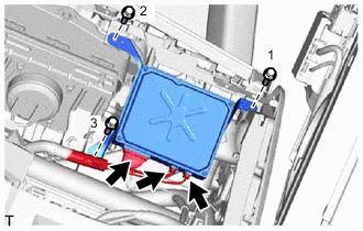
Connect all the connectors.
-
Install the telematics transceiver with the 3 bolts.
Tech Tips
Tighten the bolts in the order shown in the illustration.
-
-
INSTALL GLOVE COMPARTMENT DOOR ASSEMBLY
-
INSTALL NO. 2 INSTRUMENT PANEL UNDER COVER SUB-ASSEMBLY
-
INSTALL INSTRUMENT SIDE PANEL RH
-
INSTALL FRONT DOOR OPENING TRIM COVER RH
-
INSTALL FRONT DOOR SCUFF PLATE RH
-
INSTALL INSTRUMENT PANEL FINISH PANEL END RH
-
INSTALL CENTER INSTRUMENT CLUSTER FINISH PANEL
-
CONNECT CABLE TO NEGATIVE AUXILIARY BATTERY TERMINAL
Note
When disconnecting the cable, some systems need to be initialized after the cable is reconnected Click here.
-
INSTALL LUGGAGE COMPARTMENT TRIM COVER LH
-
INSTALL LUGGAGE COMPARTMENT FLOOR MAT
-
CHECK SRS WARNING LIGHT
-
REGISTRATION TELEMATICS TRANSCEIVER
-
When replacing the multi-media module receiver assembly or telematics transceiver, perform the vehicle contract setting Click here.
-