AUDIO AND VISUAL SYSTEM, Diagnostic DTC:B1575
| DTC Code | DTC Name |
|---|---|
| B1575 | GVIF Disconnected (from EMV/MM Integrated Device to Multi Display) |
DESCRIPTION
| DTC Code | DTC Detection Condition | Trouble Area |
|---|---|---|
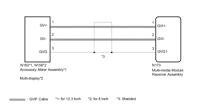
| B1575 | GVIF disconnected (from multi-media module receiver assembly to accessory meter assembly*1 or multi-display*2.) |
|
-
*1: for 12.3 Inch
-
*2: for 8 Inch
WIRING DIAGRAM
PROCEDURE
-
CLEAR DTC
-
Clear the DTCs Click here.
NEXT 
-
-
CHECK DTC
-
Recheck for DTCs and check if the same DTC is output again Click here.
OK No DTCs are output.
OK 
USE SIMULATION METHOD TO CHECK Click here
NG
-
-
CHECK HARNESS AND CONNECTOR (GVIF CABLE)
-
Check that the digital signal lines between the accessory meter assembly and multi-media module receiver assembly are not sharply bent or pinched, and that the connectors are properly connected and there are no other installation problems.
OK There are no installation problems.
NG
REPLACE HARNESS AND CONNECTOR (GVIF CABLE)
OK
-
-
CHECK HARNESS AND CONNECTOR (GVIF CABLE)
-
for 12.3 Inch
-
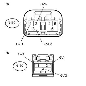
Disconnect the N150 accessory meter assembly connector.
-
Disconnect the N170 multi-media module receiver assembly connector.
-
Measure the resistance according to the value(s) in the table below.
Standard Resistance Tester Connection Condition Specified Condition N150-1 (GV+) - N170-1 (GVI+) Always Below 1 Ω N150-2 (GV-) - N170-2 (GVI-) Always Below 1 Ω N150-3 (GVG) - LN170-3 (GVG1) Always Below 1 Ω N150-1 (GV+) - Body ground Always 10 kΩ or higher N150-2 (GV-) - Body ground Always 10 kΩ or higher N150-3 (GVG) - Body ground Always 10 kΩ or higher Text in Illustration *a Front view of wire harness connector
(to Multi-media Module Receiver Assembly)
*b Front view of wire harness connector
(to Accessory Meter Assembly)
-
-
for 8 Inch
-
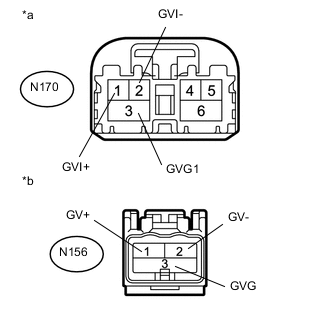
Disconnect the N156 multi-display connector.
-
Disconnect the N170 multi-media module receiver assembly connector.
-
Measure the resistance according to the value(s) in the table below.
Standard Resistance Tester Connection Condition Specified Condition N156-1 (GV+) - N170-1 (GVI+) Always Below 1 Ω N156-2 (GV-) - N170-2 (GVI-) Always Below 1 Ω N156-3 (GVG) - N170-3 (GVG1) Always Below 1 Ω N156-1 (GV+) - Body ground Always 10 kΩ or higher N156-2 (GV-) - Body ground Always 10 kΩ or higher N156-3 (GVG) - Body ground Always 10 kΩ or higher Text in Illustration *a Front view of wire harness connector
(to Multi-media Module Receiver Assembly)
*b Front view of wire harness connector
(to Multi-display)
-
OK
REPLACE MULTI-MEDIA MODULE RECEIVER ASSEMBLY Click here
NG
REPLACE HARNESS AND CONNECTOR (GVIF CABLE)
-