LIGHTING SYSTEM TERMINALS OF ECU
-
CHECK COWL SIDE JUNCTION BLOCK LH, MAIN BODY ECU (MULTIPLEX NETWORK BODY ECU)
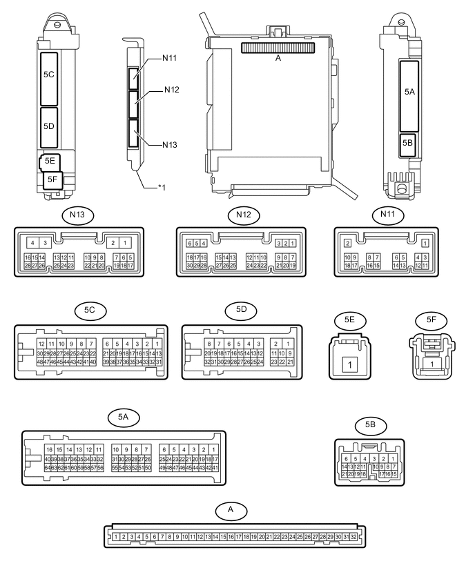
Text in Illustration *1 Main Body ECU (Multiplex Network Body ECU) - -
-
Remove the main body ECU from the cowl side junction block LH Click here.
-
Connect the cowl side junction block LH connectors.
-
Measure the resistance and voltage according to the value(s) in the table below.
Terminal No. (Symbol) Wiring Color Terminal Description Condition Specified Condition A-32 (IG) - Body ground - Ignition power supply Power switch on (IG) 11 to 14 V Power switch off Below 1 V A-30 (BECU) - Body ground - Battery power supply Power switch off 11 to 14 V A-29 (ACC) - Body ground - ACC power supply Power switch on (ACC) 11 to 14 V Power switch off Below 1 V A-11 (GND1) - Body ground - Ground Always Below 1 Ω -
Install the main body ECU Click here.
-
Measure the voltage according to the value(s) in the table below.
Terminal No. (Symbol) Wiring Color Terminal Description Condition Specified Condition N12-5 (HU) - Body ground P - Body ground Headlight dimmer switch high signal input Headlight dimmer switch in high position Below 1 V Headlight dimmer switch in low position 11 to 14 V N12-8 (HF) - Body ground L - Body ground Headlight dimmer switch high flash signal input Headlight dimmer switch in high flash position Below 1 V Headlight dimmer switch not in high flash position 11 to 14 V N12-28 (A) - Body ground R - Body ground Headlight dimmer switch AUTO signal input Headlight dimmer switch in AUTO position Below 1 V Headlight dimmer switch not in AUTO position 11 to 14 V N12-29 (HEAD) - Body ground LG - Body ground Headlight dimmer switch head signal input Headlight dimmer switch in head position Below 1 V Headlight dimmer switch not in head position 11 to 14 V N12-30 (TAIL) - Body ground B - Body ground Headlight dimmer switch tail signal input Headlight dimmer switch in tail or head position Below 1 V Headlight dimmer switch in neither tail nor head position 11 to 14 V N12-20 (CLTB) - N12-22 (CLTE) GR - W Automatic light control sensor power supply output Power switch off Below 1 V Power switch on (IG) and headlight dimmer switch in AUTO position 11 to 14 V N12-21 (CLTS) - Body ground R - Body ground Automatic light control sensor signal input Power switch off Below 1 V Power switch on (IG)
Headlight dimmer switch in AUTO position
Automatic light control sensor covered with a hand → Automatic light control sensor exposed to ambient light
Pulse generation
(See waveform)
N12-27 (FFOG) - Body ground*1 Y - Body ground Front fog light switch input Front fog light switch on Below 1 V Front fog light switch off 11 to 14 V N13-17 (AHBI) - Body ground*2, *6 Y - Body ground Automatic high beam main switch input Automatic high beam main switch on Below 1 V Automatic high beam main switch off 11 to 14 V N13-23 (RFOG) - Body ground*3 GR - Body ground Rear fog light switch input Rear fog light switch on Below 1 V Rear fog light switch off 11 to 14 V 5D-9 (HRLY) - Body ground Y - Body ground LP LAMP relay drive output Headlight dimmer switch in head position Below 1 V Headlight dimmer switch not in head position 11 to 14 V 5D-11 (TRLY) - Body ground R - Body ground No. 2 integration relay (TAIL relay) drive output Headlight dimmer switch in tail position Below 1 V Headlight dimmer switch not in tail position 11 to 14 V 5D-21 (DIM) - Body ground LG - Body ground No. 2 integration relay (DIMMER relay) drive output Headlight dimmer switch in high or high flash position Below 1 V Headlight dimmer switch not in high or high flash position 11 to 14 V 5D-22 (FFGO) - Body ground*1 GR - Body ground Front fog light signal output Headlight dimmer switch in tail position and front fog light switch on Below 1 V Front fog light switch off 11 to 14 V 5C-16 (RFGO) - Body ground*3 GR - Body ground Rear fog light signal output Headlight dimmer switch in tail position and rear fog light switch on Below 1 V Rear fog light switch off 11 to 14 V
-
*1: w/ Front Fog Light
-
*2: w/ Automatic High Beam System
-
*3: w/ Rear Fog Light
-
*4: for LHD
-
*5: for RHD
-
*6: w/ Adaptive High Beam System
-
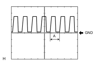
Waveform
Item Content Terminal No. (Symbol) N12-21 (CLTS) - Body ground Tool setting 5 V/DIV., 5 ms./DIV. Condition Power switch on (IG)
Headlight dimmer switch in AUTO position
Automatic light control sensor covered with a hand → Automatic light control sensor exposed to ambient light
Tech Tips
If the ambient light becomes brighter, width A becomes narrower.
-
-
-
CHECK HEADLIGHT ECU SUB-ASSEMBLY LH (for Single Beam Headlight)
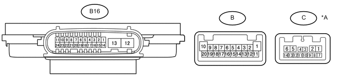
Text in Illustration *A w/ AFS (Adaptive Front-lighting System) - -
-
Disconnect the B16 headlight ECU sub-assembly LH connector.
-
Measure the voltage and resistance according to the value(s) in the table below.
Terminal No. (Symbol) Wiring Color Terminal Description Condition Specified Condition B16-4 (IG) - Body ground LG - Body ground Ignition power supply Power switch on (IG) 11 to 14 V Power switch off Below 1 V B16-13 (ECUB) - Body ground G - Body ground Battery power supply Power switch on (IG) 11 to 14 V Power switch off Below 1 V B16-12 (GND) - Body ground W-B - Body ground Ground Always Below 1 Ω -
Reconnect the B16 headlight ECU sub-assembly LH connector.
Tech Tips
-
Since the B16 headlight ECU sub-assembly LH connector is a waterproof type connector, the voltage and pulses cannot be checked directly. The values listed are for reference only.
-
Since the B headlight ECU sub-assembly LH connector is connected inside the headlight assembly, the voltage and pulses cannot be checked directly. The values listed are for reference only.
-
-
Measure the voltage and check of pulses according to the value(s) in the table below.
w/o AFS (Adaptive Front-lighting System) Terminal No. (Symbol) Wiring Color Terminal Description Condition Specified Condition B16-11 (TNS) - Body ground W - Body ground Left turn signal light signal input Power switch on (IG), left turn signal light off Below 1 V Power switch on (IG), left turn signal light blinking 11 to 14 V ←→ Below 1 V B16-16 (SBR) - B16-15 (SGR) R - B Rear height control sensor sub-assembly LH power supply Power switch on (IG) 4.75 to 5.25 V B16-17 (SHRL) - B16-15 (SGR) P - B Rear height control sensor sub-assembly LH signal input Power switch on (IG), vehicle unloaded, vehicle stopped Approximately 2.5 V
(value decreases as the front of the vehicle is raised)
B16-20 (LINL) - Body ground B - Body ground LIN communication Power switch on (IG) Pulse generation Power switch off Below 1 V B-1 - B-10 - Low beam headlights/high beam headlights switching signal output High beam headlights off Below 1 V High beam headlights on 11 to 14 V B-4 - B-5 - Headlight light signal output High beam and low beam headlights off Below 1 V High beam or low beam headlights on 11.2 to 17.7 V B-6 - B-14 - Headlight light signal output Low beam headlights off Below 1 V Low beam headlights on 4.5 to 5.5 V B-7 - B-17 - Headlight leveling motor power source Power switch off Below 1 V Power switch on (IG) 11 to 14 V B-8 - B-17 - Headlight leveling motor power source Power switch on (IG), when low beam headlights turn on, vehicle height not changed Below 1 V Power switch on (IG), when low beam headlights turn on, vehicle height changed and maintained for more than 3 seconds 11 to 14 V B-9 - B-13 - Left turn signal light signal input Power switch on (IG), left turn signal light off Below 1 V Power switch on (IG), left turn signal light blinking 11 to 14 V ←→ Below 1 V B-11 - B-16 - Daytime running lights/clearance lights duty control signal output Daytime running lights and clearance lights off Below 1 V Daytime running lights or clearance lights on Pulse generation B-15 - B-14 - Headlight fan duty control signal input Low beam headlights off Below 1 V Low beam headlights on Pulse generation B-11 - B-20 - Daytime running lights/clearance lights power source Daytime running lights and clearance lights off Below 1 V Daytime running lights or clearance lights on 11 to 14 V w/ AFS (Adaptive Front-lighting System) Terminal No. (Symbol) Wiring Color Terminal Description Condition Specified Condition B16-11 (TNS) - Body ground W - Body ground Left turn signal light signal input Power switch on (IG), left turn signal light off Below 1 V Power switch on (IG), left turn signal light blinking 11 to 14 V ←→ Below 1 V B16-16 (SBR) - B16-15 (SGR) R - B Rear height control sensor sub-assembly LH power supply Power switch on (IG) 4.75 to 5.25 V B16-17 (SHRL) - B16-15 (SGR) P - B Rear height control sensor sub-assembly LH signal input Power switch on (IG), vehicle unloaded, vehicle stopped Approximately 2.5 V
(value decreases as the front of the vehicle is raised)
B16-19 (LINS) - Body ground L - Body ground LIN communication Power switch on (IG) Pulse generation Power switch off Below 1 V B16-21 (LCL) - Body ground W - Body ground CAN communication Power switch on (IG) Pulse generation Power switch off Below 1 V B16-22 (LCH) - Body ground Y - Body ground CAN communication Power switch on (IG) Pulse generation Power switch off Below 1 V B-1 - B-10 - Low beam headlights/high beam headlights switching signal output High beam headlights off Below 1 V High beam headlights on 11 to 14 V B-4 - B-3 - Headlight light signal output High beam and low beam headlights off Below 1 V High beam or low beam headlights on 11.2 to 17.7 V B-6 - B-14 - Headlight light signal output Low beam headlights off Below 1 V Low beam headlights on 4.5 to 5.5 V B-7 - B-17 - Headlight leveling motor power source Power switch off Below 1 V Power switch on (IG) 11 to 14 V C-13 - B-17 - Headlight leveling motor power source Power switch on (IG), when low beam headlights turn on, vehicle height not changed Below 1 V Power switch on (IG), when low beam headlights turn on, vehicle height changed and maintained for more than 3 seconds 11 to 14 V B-9 - B-13 - Left turn signal light signal input Power switch on (IG), left turn signal light off Below 1 V Power switch on (IG), left turn signal light blinking 11 to 14 V ←→ Below 1 V B-11 - B-16 - Daytime running lights/clearance lights duty control signal output Daytime running lights and clearance lights off Below 1 V Daytime running lights or clearance lights on Pulse generation B-15 - B-14 - Headlight fan duty control signal input Low beam headlights off Below 1 V Low beam headlights on Pulse generation B-11 - B-20 - Daytime running lights/clearance lights power source Daytime running lights and clearance lights off Below 1 V Daytime running lights or clearance lights on 11 to 14 V
-
-
CHECK HEADLIGHT ECU SUB-ASSEMBLY RH (for Single Beam Headlight)

Text in Illustration *A w/ AFS (Adaptive Front-lighting System) - -
-
Disconnect the B15 headlight ECU sub-assembly RH connector.
-
Measure the voltage and resistance according to the value(s) in the table below.
Terminal No. (Symbol) Wiring Color Terminal Description Condition Specified Condition B15-4 (IG) - Body ground LG - Body ground Ignition power supply Power switch on (IG) 11 to 14 V Power switch off Below 1 V B15-13 (ECUB) - Body ground B - Body ground Battery power supply Power switch on (IG) 11 to 14 V Power switch off Below 1 V B15-12 (GND) - Body ground W-B - Body ground Ground Always Below 1 Ω -
Reconnect the B15 headlight ECU sub-assembly RH connector.
Tech Tips
-
Since the B15 headlight ECU sub-assembly RH connector is a waterproof type connector, the voltage and pulses cannot be checked directly. The values listed are for reference only.
-
Since the B headlight ECU sub-assembly RH connector is connected inside the headlight assembly, the voltage and pulses cannot be checked directly. The values listed are for reference only.
-
-
Measure the voltage and check of pulses according to the value(s) in the table below.
w/o AFS (Adaptive Front-lighting System) Terminal No. (Symbol) Wiring Color Terminal Description Condition Specified Condition B15-11 (TNS) - Body ground Y - Body ground Right turn signal light signal input Power switch on (IG), right turn signal light off Below 1 V Power switch on (IG), right turn signal light blinking 11 to 14 V ←→ Below 1 V B15-20 (LINL) - Body ground B - Body ground LIN communication Power switch on (IG) Pulse generation Power switch off Below 1 V B-1 - B-10 - Low beam headlights/high beam headlights switching signal output High beam headlights off Below 1 V High beam headlights on 11 to 14 V B-4 - B-5 - Headlight light signal output High beam and low beam headlights off Below 1 V High beam or low beam headlights on 11.2 to 17.7 V B-6 - B-14 - Headlight light signal output Low beam headlights off Below 1 V Low beam headlights on 4.5 to 5.5 V B-7 - B-17 - Headlight leveling motor power source Power switch off Below 1 V Power switch on (IG) 11 to 14 V B-8 - B-17 - Headlight leveling motor power source Power switch on (IG), when low beam headlights turn on, vehicle height not changed Below 1 V Power switch on (IG), when low beam headlights turn on, vehicle height changed and maintained for more than 3 seconds 11 to 14 V B-9 - B-13 - Left turn signal light signal input Power switch on (IG), left turn signal light off Below 1 V Power switch on (IG), left turn signal light blinking 11 to 14 V ←→ Below 1 V B-11 - B-16 - Daytime running lights/clearance lights duty control signal output Daytime running lights and clearance lights off Below 1 V Daytime running lights or clearance lights on Pulse generation B-15 - B-14 - Headlight fan duty control signal input Low beam headlights off Below 1 V Low beam headlights on Pulse generation B-11 - B-20 - Daytime running lights/clearance lights power source Daytime running lights and clearance lights off Below 1 V Daytime running lights or clearance lights on 11 to 14 V w/ AFS (Adaptive Front-lighting System) Terminal No. (Symbol) Wiring Color Terminal Description Condition Specified Condition B15-11 (TNS) - Body ground Y - Body ground Right turn signal light signal input Power switch on (IG), right turn signal light off Below 1 V Power switch on (IG), right turn signal light blinking 11 to 14 V ←→ Below 1 V B15-20 (LINL) - Body ground B - Body ground LIN communication Power switch on (IG) Pulse generation Power switch off Below 1 V B15-21 (LCL) - Body ground W - Body ground CAN communication Power switch on (IG) Pulse generation Power switch off Below 1 V B15-22 (LCH) - Body ground Y - Body ground CAN communication Power switch on (IG) Pulse generation Power switch off Below 1 V B-1 - B-10 - Low beam headlights/high beam headlights switching signal output High beam headlights off Below 1 V High beam headlights on 11 to 14 V B-4 - B-3 - Headlight light signal output High beam and low beam headlights off Below 1 V High beam or low beam headlights on 11.2 to 17.7 V B-6 - B-14 - Headlight light signal output Low beam headlights off Below 1 V Low beam headlights on 4.5 to 5.5 V B-7 - B-17 - Headlight leveling motor power source Power switch off Below 1 V Power switch on (IG) 11 to 14 V C-13 - B-17 - Headlight leveling motor power source Power switch on (IG), when low beam headlights turn on, vehicle height not changed Below 1 V Power switch on (IG), when low beam headlights turn on, vehicle height changed and maintained for more than 3 seconds 11 to 14 V B-9 - B-13 - Left turn signal light signal input Power switch on (IG), left turn signal light off Below 1 V Power switch on (IG), left turn signal light blinking 11 to 14 V ←→ Below 1 V B-11 - B-16 - Daytime running lights/clearance lights duty control signal output Daytime running lights and clearance lights off Below 1 V Daytime running lights or clearance lights on Pulse generation B-15 - B-14 - Headlight fan duty control signal input Low beam headlights off Below 1 V Low beam headlights on Pulse generation B-11 - B-20 - Daytime running lights/clearance lights power source Daytime running lights and clearance lights off Below 1 V Daytime running lights or clearance lights on 11 to 14 V
-
-
CHECK HEADLIGHT ECU SUB-ASSEMBLY LH (for Triple Beam Headlight)

-
Disconnect the B16 headlight ECU sub-assembly LH connector.
-
Measure the voltage and resistance according to the value(s) in the table below.
Terminal No. (Symbol) Wiring Color Terminal Description Condition Specified Condition B16-4 (IG) - Body ground LG - Body ground Ignition power supply Power switch on (IG) 11 to 14 V Power switch off Below 1 V B16-13 (ECUB) - Body ground G - Body ground Battery power supply Power switch on (IG) 11 to 14 V Power switch off Below 1 V B16-12 (GND) - Body ground W-B - Body ground Ground Always Below 1 Ω -
Reconnect the B16 headlight ECU sub-assembly LH connector.
Tech Tips
-
Since the B16 headlight ECU sub-assembly LH connector is a waterproof type connector, the voltage and pulses cannot be checked directly. The values listed are for reference only.
-
Since the B headlight ECU sub-assembly LH connector is connected inside the headlight assembly, the voltage and pulses cannot be checked directly. The values listed are for reference only.
-
-
Measure the voltage and check of pulses according to the value(s) in the table below.
Terminal No. (Symbol) Wiring Color Terminal Description Condition Specified Condition B16-11 (TNS) - Body ground W - Body ground Left turn signal light signal input Power switch on (IG), left turn signal light off Below 1 V Power switch on (IG), left turn signal light blinking 11 to 14 V ←→ Below 1 V B16-16 (SBR) - B16-15 (SGR) R - B Rear height control sensor sub-assembly LH power supply Power switch on (IG) 4.75 to 5.25 V B16-17 (SHRL) - B16-15 (SGR) P - B Rear height control sensor sub-assembly LH signal input Power switch on (IG), vehicle unloaded, vehicle stopped Approximately 2.5 V
(value decreases as the front of the vehicle is raised)
B16-21 (LCL) - Body ground W - Body ground CAN communication Power switch on (IG) Pulse generation Power switch off Below 1 V B16-22 (LCH) - Body ground Y - Body ground CAN communication Power switch on (IG) Pulse generation Power switch off Below 1 V B-1 - B-10*1 - Low beam headlights/high beam headlights switching signal output Power switch off Below 1 V Power switch on (IG) 11 to 14 V B-3 - B-4 - Low beam headlights drive output Low beam headlights off Below 1 V Low beam headlights on 16.05 to 25.65 V B-6 - B-14 - Headlight light signal output Low beam headlights off Below 1 V Low beam headlights on 4.5 to 5.5 V B-7 - B-17 - Headlight leveling motor power source Power switch off Below 1 V Power switch on (IG) 11 to 14 V B-9 - B-13 - Left turn signal light signal input Power switch on (IG), left turn signal light off Below 1 V Power switch on (IG), left turn signal light blinking 11 to 14 V ←→ Below 1 V B-11 - B-16 - Daytime running lights/clearance lights duty control signal output Daytime running lights and clearance lights off Below 1 V Daytime running lights or clearance lights on Pulse generation B-15 - B-14 - Headlight fan duty control signal input Low beam headlights off Below 1 V Low beam headlights on Pulse generation B-11 - B-20 - Daytime running lights/clearance lights power source Daytime running lights and clearance lights off Below 1 V Daytime running lights or clearance lights on 11 to 14 V C-7 - C-8 - High beam headlights drive output Hi beam headlights off Below 1 V Hi beam headlights on 6 to 15 V*1
16.05 to 25.65 V*2
C-13 - Body ground - Headlight leveling motor signal output Low beam headlights off Below 1 V Low beam headlights on Pulse generation
-
*1: w/ Adaptive High Beam System
-
*2: w/o Adaptive High Beam System
-
-
-
CHECK HEADLIGHT ECU SUB-ASSEMBLY RH (for Triple Beam Headlight)

-
Disconnect the B15 headlight ECU sub-assembly RH connector.
-
Measure the voltage and resistance according to the value(s) in the table below.
Terminal No. (Symbol) Wiring Color Terminal Description Condition Specified Condition B15-4 (IG) - Body ground LG - Body ground Ignition power supply Power switch on (IG) 11 to 14 V Power switch off Below 1 V B15-13 (ECUB) - Body ground B - Body ground Battery power supply Power switch on (IG) 11 to 14 V Power switch off Below 1 V B15-12 (GND) - Body ground W-B - Body ground Ground Always Below 1 Ω -
Reconnect the B15 headlight ECU sub-assembly RH connector.
Tech Tips
-
Since the B15 headlight ECU sub-assembly RH connector is a waterproof type connector, the voltage and pulses cannot be checked directly. The values listed are for reference only.
-
Since the B headlight ECU sub-assembly RH connector is connected inside the headlight assembly, the voltage and pulses cannot be checked directly. The values listed are for reference only.
-
-
Measure the voltage and check of pulses according to the value(s) in the table below.
Terminal No. (Symbol) Wiring Color Terminal Description Condition Specified Condition B15-11 (TNS) - Body ground Y - Body ground Right turn signal light signal input Power switch on (IG), right turn signal light off Below 1 V Power switch on (IG), right turn signal light blinking 11 to 14 V ←→ Below 1 V B15-21 (LCL) - Body ground W - Body ground CAN communication Power switch on (IG) Pulse generation Power switch off Below 1 V B15-22 (LCH) - Body ground Y - Body ground CAN communication Power switch on (IG) Pulse generation Power switch off Below 1 V B-1 - B-10*1 - Low beam headlights/high beam headlights switching signal output Power switch off Below 1 V Power switch on (IG) 11 to 14 V B-3 - B-4 - Low beam headlights drive output Low beam headlights off Below 1 V Low beam headlights on 16.05 to 25.65 V B-6 - B-14 - Headlight light signal output Low beam headlights off Below 1 V Low beam headlights on 4.5 to 5.5 V B-7 - B-17 - Headlight leveling motor power source Power switch off Below 1 V Power switch on (IG) 11 to 14 V B-9 - B-13 - Left turn signal light signal input Power switch on (IG), left turn signal light off Below 1 V Power switch on (IG), left turn signal light blinking 11 to 14 V ←→ Below 1 V B-11 - B-16 - Daytime running lights/clearance lights duty control signal output Daytime running lights and clearance lights off Below 1 V Daytime running lights or clearance lights on Pulse generation B-15 - B-14 - Headlight fan duty control signal input Low beam headlights off Below 1 V Low beam headlights on Pulse generation B-11 - B-20 - Daytime running lights/clearance lights power source Daytime running lights and clearance lights off Below 1 V Daytime running lights or clearance lights on 11 to 14 V C-7 - C-8 - High beam headlights drive output Hi beam headlights off Below 1 V Hi beam headlights on 6 to 15 V*1
16.05 to 25.65 V*2
C-13 - Body ground - Headlight leveling motor signal output Low beam headlights off Below 1 V Low beam headlights on Pulse generation
-
*1: w/ Adaptive High Beam System
-
*2: w/o Adaptive High Beam System
-
-
-
CHECK COMBINATION METER ASSEMBLY Click here