WIPER AND WASHER SYSTEM TERMINALS OF ECU
-
CHECK WINDSHIELD WIPER SWITCH ASSEMBLY
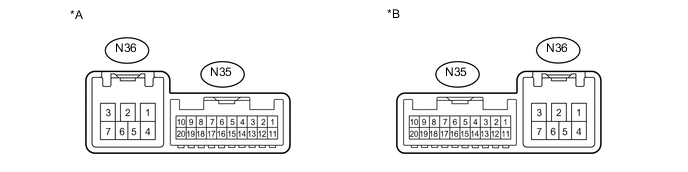
Text in Illustration *A for Windshield Wiper Switch (LH Side) *B for Windshield Wiper Switch (RH Side)
-
Disconnect the N35 and N36 windshield wiper switch assembly connectors.
-
Measure the voltage and resistance according to the value(s) in the table below.
Terminal No. (Symbol) Wiring Color Terminal Description Condition Specified Condition N35-2 (+B) - Body ground SB - Body ground IG power source Power switch on (IG) 11 to 14 V Power switch off Below 1 V N35-7 (E) - Body ground W-B - Body ground Ground Always Below 1 Ω N36-4 (EW) - Body ground*1 W-B - Body ground Ground Always Below 1 Ω N36-7 (EW) - Body ground*2 W-B - Body ground Ground Always Below 1 Ω
-
*1: for Windshield Wiper Switch (RH Side)
-
*2: for Windshield Wiper Switch (LH Side)
If the result is not as specified, there may be a malfunction in the wire harness.
-
-
Reconnect the N35 and N36 windshield wiper switch assembly connectors.
-
Measure the voltage according to the value(s) in the table below.
Terminal No. (Symbol) Wiring Color Terminal Description Condition Specified Condition N35-3 (TAIL) - Body ground*1 G - Body ground Headlight dimmer switch position signal Power switch on (IG), headlight dimmer switch in off position 11 to 14 V Power switch on (IG), headlight dimmer switch in tail or head position Below 1 V N35-4 (RLY2) - Body ground P - Body ground INT relay operation signal Power switch on (IG), wiper switch in off position 11 to 14 V Power switch on (IG), wiper switch in HI operation position Below 1 V N35-5 (RLY1) - Body ground GR - Body ground Windshield wiper relay operation signal Power switch on (IG), wiper switch in off position 11 to 14 V Power switch on (IG), wiper switch in LO operation position Below 1 V N35-8 (MPX1) - Body ground*1 LG - Body ground LIN communication signal Power switch on (IG) Pulse generation N35-10 (CSS+) - N35-9 (CSS-) L - LG Vehicle speed signal Driving at approximately 20 km/h (12 mph) Pulse generation N35-20 (+S) - Body ground Y - Body ground Wiper motor operation signal Power switch on (IG), wiper switch in off position 11 to 14 V Power switch on (IG), wiper switch in LO or HI operation position Below 1 V N36-4 (WF) - Body ground*3 B - Body ground Washer motor operation signal Power switch on (IG), washer switch in off position 11 to 14 V Power switch on (IG), washer switch in on position Below 1 V N36-7 (WF) - Body ground*2 B - Body ground Washer motor operation signal Power switch on (IG), washer switch in off position 11 to 14 V Power switch on (IG), washer switch in on position Below 1 V
-
*1: w/ Rain Sensor
-
*2: for Windshield Wiper Switch (RH Side)
-
*3: for Windshield Wiper Switch (LH Side)
-
-
-
CHECK COWL SIDE JUNCTION BLOCK LH, MAIN BODY ECU (MULTIPLEX NETWORK BODY ECU)
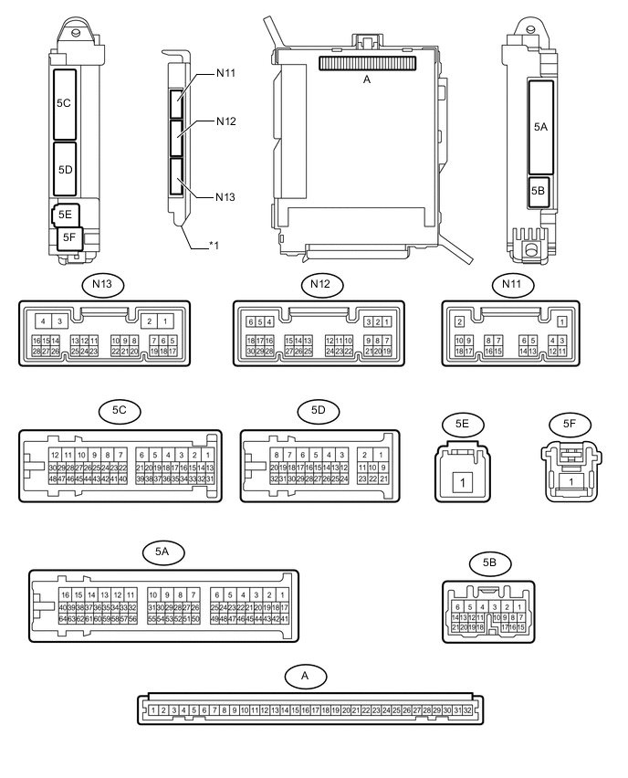
Text in Illustration *1 Main Body ECU (Multiplex Network Body ECU) - -
-
Remove the main body ECU (multiplex network body ECU) from the cowl side junction block LH Click here.
-
Connect the cowl side junction block LH connectors.
-
Measure the resistance and voltage according to the value(s) in the table below.
Terminal No. (Symbol) Wiring Color Terminal Description Condition Specified Condition A-32 (IG) - Body ground - IG power source Power switch on (IG) 11 to 14 V A-30 (BECU) - Body ground - Auxiliary battery power source Always 11 to 14 V A-29 (ACC) - Body ground - ACC power source Power switch on (ACC) 11 to 14 V A-11 (GND1) - Body ground - Ground Always Below 1 Ω -
Install the main body ECU (multiplex network body ECU) Click here.
-
Measure the voltage according to the value(s) in the table below.
Terminal No. (Symbol) Wiring Color Terminal Description Condition Specified Condition 5A-44 (HRLY) - Body ground GR - Body ground H-LP LO relay drive output signal Headlight dimmer switch not in head position 11 to 14 V Headlight dimmer switch in head position Below 1 V 5A-59 (ACAN) - Body ground G - Body ground Headlight dimmer switch position signal Power switch on (IG), headlight dimmer switch in neither tail nor head position 11 to 14 V Power switch on (IG), headlight dimmer switch in tail or head position Below 1 V 5D-9 (HRLY) - Body ground Y - Body ground H-LP LO relay drive output signal Headlight dimmer switch not in head position 11 to 14 V Headlight dimmer switch in head position Below 1 V
-
-
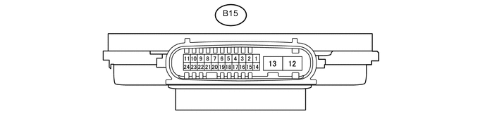
CHECK HEADLIGHT ECU SUB-ASSEMBLY RH (w/ Headlight Cleaner System)
-
Disconnect the B15 headlight ECU sub-assembly RH connector.
-
Measure the resistance and voltage on the wire harness side connector according to the value(s) in the table below.
Terminal No. (Symbol) Wiring Color Terminal Description Condition Specified Condition B15-4 (IG) - Body ground LG - Body ground Ignition power supply Power switch off Below 1 V Power switch on (IG) 11 to 14 V B15-12 (GND) - Body ground W-B - Body ground Ground Always Below 1 Ω -
Reconnect the B15 headlight ECU sub-assembly RH connector.
Tech Tips
Since the headlight ECU sub-assembly RH uses a waterproof connector, the voltage and pulses cannot be checked directly. The values listed are for reference only.
-
Measure the voltage and check of pulses according to the value(s) in the table below.
Terminal No. (Symbol) Wiring Color Terminal Description Condition Specified Condition B15-7(HLC) - Body ground G - Body ground Headlight cleaner motor operation signal Power switch on (IG), when low beam headlights turn on, Headlight cleaner motor not operating 11 to 14 V Power switch on (IG), when low beam headlights turn on, Headlight cleaner motor operating Below 1 V B15-18(FRWA) - Body ground R - Body ground Font washer switch signal Power switch on (IG), front washer switch on 11 to 14 V Power switch on (IG), front washer switch off Below 1 V
-