INSTRUMENT PANEL SAFETY PAD INSTALLATION
CAUTION / NOTICE / HINT
Tech Tips
-
Use the same procedure for RHD and LHD vehicles.
-
The procedure listed below is for LHD vehicles.
-
A bolt without a torque specification is shown in the standard bolt chart Click here.
PROCEDURE
-
INSTALL GLOVE COMPARTMENT DOOR LOCK COVER
-
Attach the 3 claws to install the glove compartment door lock cover.
-
-
INSTALL GLOVE COMPARTMENT DOOR LOCK ASSEMBLY
-
Install the glove compartment door lock assembly with the 2 screws <A>.
-
-
INSTALL INSTRUMENT PANEL SAFETY PAD SUB-ASSEMBLY
-
w/ Headup Display:
-
Attach the 2 guides to install the instrument safety pad sub-assembly.
-
Install the 2 passenger airbag bolts <F>.
- Torque:
- 20 N*m { 204 kgf*cm, 15 ft.*lbf }
-
Install the 2 bolts <C>, nut <D> and 2 bolts <E>.
-
Attach the 2 claws to connect the room temperature sensor.
-
Connect the connectors and attach the clamp.
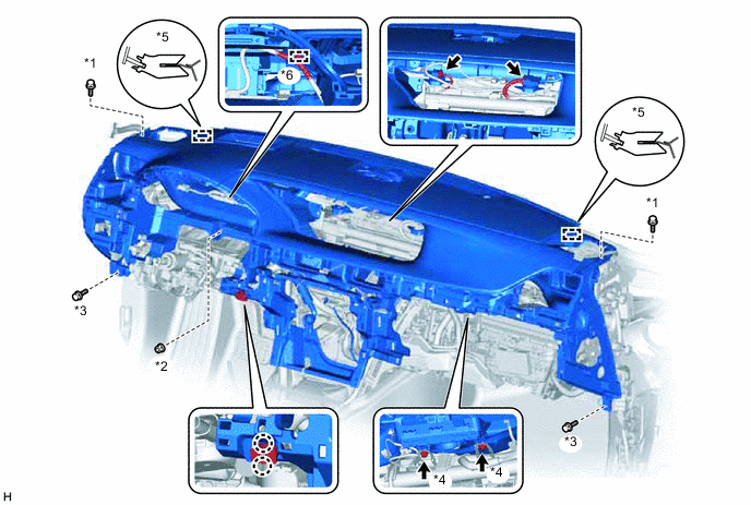
Text in Illustration *1 Bolt <C> *2 Nut <D> *3 Bolt <E> *4 Bolt <F> *5 Guide *6 Clamp
-
-
w/o Headup Display:
-
Attach the 2 guides to install the instrument safety pad sub-assembly.
-
Install the 2 passenger airbag bolts <F>.
- Torque:
- 20 N*m { 204 kgf*cm, 15 ft.*lbf }
-
Install the 2 bolts <C>, nut <D> and 2 bolts <E>.
-
Attach the 2 claws to connect the room temperature sensor.
-
Connect the connectors and attach the clamp.
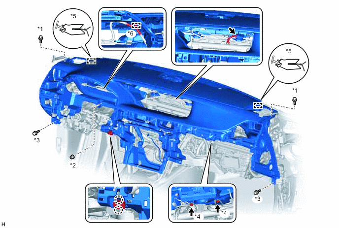
Text in Illustration *1 Bolt <C> *2 Nut <D> *3 Bolt <E> *4 Bolt <F> *5 Guide *6 Clamp
-
-
-
INSTALL MULTI-DISPLAY (for 8 Inch)
-
INSTALL ACCESSORY METER ASSEMBLY (for 12.3 Inch)
-
INSTALL UPPER INSTRUMENT CLUSTER FINISH PANEL
-
Attach the 2 clips and 3 claws to install the upper instrument cluster finish panel.
-
Install the 3 clips <B>.
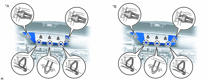
Text in Illustration *A for 12.3 Inch *B for 8 Inch
-
-
INSTALL FRONT NO. 3 SPEAKER ASSEMBLY
-
INSTALL NO. 1 SPEAKER OPENING COVER ASSEMBLY
-
Attach the claw, 4 clips and guide to install the No. 1 speaker opening cover assembly.
-
-
INSTALL FRONT NO. 2 SPEAKER ASSEMBLY
-
INSTALL NO. 1 INSTRUMENT PANEL SPEAKER PANEL SUB-ASSEMBLY
-
Attach the 2 clips and 2 guides to install the No. 1 instrument panel speaker panel sub-assembly.
-
-
INSTALL NO. 2 INSTRUMENT PANEL SPEAKER PANEL SUB-ASSEMBLY
-
Attach the 2 clips and 2 guides to install the No. 2 instrument panel speaker panel sub-assembly.
-
-
INSTALL NO. 2 INSTRUMENT PANEL GARNISH SUB-ASSEMBLY
-
Attach the 9 clips and claw to install the No. 2 instrument panel garnish sub-assembly together with the No. 3 instrument panel register assembly.
-
Install the 2 screws <G> to the back of the No. 2 instrument panel garnish sub-assembly.
-
-
INSTALL TELEMATICS TRANSCEIVER (w/ Telematics Transceiver)
-
INSTALL NO. 2 INSTRUMENT PANEL REGISTER ASSEMBLY
-
Connect the connectors.
-
Attach the 7 clips to install the No. 2 instrument panel register assembly.
-
-
INSTALL MULTI-MEDIA MODULE RECEIVER ASSEMBLY
-
INSTALL GLOVE COMPARTMENT DOOR ASSEMBLY
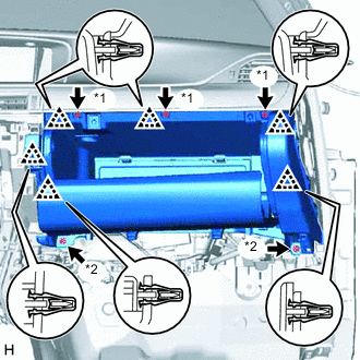
Text in Illustration *1 Screw <A> *2 Bolt <E>
-
Connect the connectors and attach the clamp.
-
Attach the 6 clips to install the glove compartment door assembly.
-
Install the 3 screws <A> and 2 bolts <E>.
-
-
INSTALL NO. 2 INSTRUMENT PANEL UNDER COVER SUB-ASSEMBLY
-
Connect the connectors and attach the clamp.
-
Attach the 5 clips and 2 guides to install the No. 2 instrument panel under cover sub-assembly.
-
-
INSTALL INSTRUMENT SIDE PANEL RH
-
w/ Airbag Cut Off Switch:
-
Connect the connector.
-
-
Attach the 7 clips to install the instrument side panel RH.
-
-
INSTALL NO. 1 INSTRUMENT PANEL REGISTER ASSEMBLY
-
Connect the connector.
-
Attach the 4 clips to install the No. 1 instrument panel register assembly.
-
-
INSTALL COMBINATION METER ASSEMBLY
-
INSTALL HEADLIGHT DIMMER SWITCH ASSEMBLY
-
INSTALL INSTRUMENT CLUSTER FINISH PANEL SUB-ASSEMBLY
-
Connect the connectors.
-
Attach the 6 clips and 6 claws to install the instrument cluster finish panel sub-assembly.
-
-
INSTALL INSTRUMENT CLUSTER FINISH PANEL ASSEMBLY
-
Attach the 9 clips and 2 guides to install the instrument cluster finish panel assembly.
-
-
INSTALL LOWER NO. 1 INSTRUMENT PANEL AIRBAG ASSEMBLY
-
INSTALL NO. 1 INSTRUMENT PANEL SAFETY PAD SUB-ASSEMBLY
-
Connect the connectors.
-
Attach the 9 clips and guide to install the No. 1 instrument panel safety pad sub-assembly.
-
-
INSTALL NO. 1 INSTRUMENT PANEL UNDER COVER SUB-ASSEMBLY
-
Connect the connectors and attach the clamp.
-
Attach the 2 claws to install the No. 1 instrument panel under cover sub-assembly.
-
Install the 3 screws <A>.
-
-
INSTALL NO. 1 INSTRUMENT PANEL GARNISH SUB-ASSEMBLY
-
Attach the 4 clips to install the No. 1 instrument panel garnish sub-assembly.
-
-
INSTALL INSTRUMENT SIDE PANEL LH
-
Attach the 7 clips to install the instrument side panel LH.
-
-
INSTALL FRONT PILLAR GARNISH LH
-
INSTALL FRONT PILLAR GARNISH RH
-
INSTALL FRONT DOOR OPENING TRIM COVER LH
-
INSTALL FRONT DOOR OPENING TRIM COVER RH
-
INSTALL FRONT DOOR SCUFF PLATE LH
-
INSTALL FRONT DOOR SCUFF PLATE RH
-
INSTALL CONSOLE BOX ASSEMBLY
-
CONNECT CABLE TO NEGATIVE AUXILIARY BATTERY TERMINAL
Note
When disconnecting the cable, some systems need to be initialized after the cable is reconnected Click here.
-
ENABLE AUTOAWAY/RETURN FUNCTION
-
Restore the autoaway/return function setting to the previous condition by changing the customize parameter Click here.
-
-
CHECK SRS WARNING LIGHT
-
INSTALL LUGGAGE COMPARTMENT TRIM COVER LH
-
INSTALL LUGGAGE COMPARTMENT FLOOR MAT