AIR CONDITIONING UNIT INSTALLATION
CAUTION / NOTICE / HINT
Tech Tips
-
Use the same procedure for RHD and LHD vehicles.
-
The procedure listed below is for LHD vehicles.
PROCEDURE
-
INSTALL AIR CONDITIONING UNIT
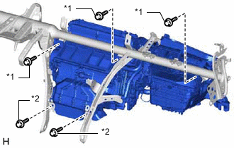
Text in Illustration *1 Bolt *2 Screw
-
Install the air conditioning unit with the 3 bolts and 2 screws.
- Torque:
- for bolt
- 9.8 N*m { 100 kgf*cm, 87 in.*lbf }
-
-
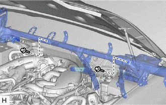
INSTALL INSTRUMENT PANEL REINFORCEMENT ASSEMBLY WITH AIR CONDITIONING UNIT ASSEMBLY
-
Install the instrument panel reinforcement assembly with air conditioning unit assembly.
-
Using a 8 mm hexagon wrench, tighten the 3 collars.
-
Install the 9 bolts.
- Torque:
- for bolt A
- 20 N*m { 204 kgf*cm, 15 ft.*lbf }
- for bolt B
- 21 N*m { 214 kgf*cm, 15 ft.*lbf }
-
Install the 6 caps.
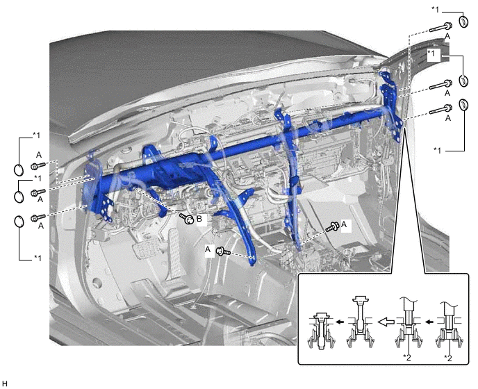
Text in Illustration *1 Cap *2 Collar -
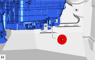
Install the nut.
- Torque:
- 9.8 N*m { 100 kgf*cm, 87 in.*lbf }
-
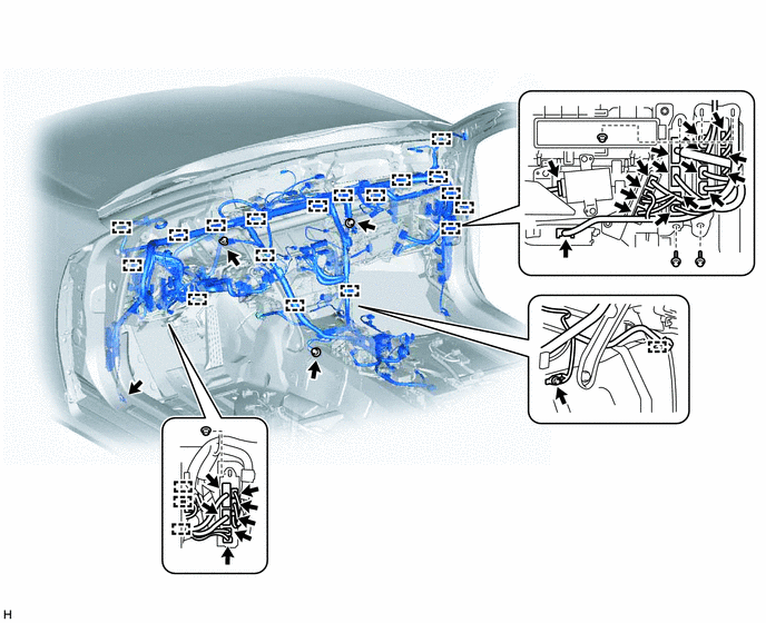
Install the bolts and nuts.
-
Attach the clamps and connect the connectors.
-
Install the 2 bolts.
- Torque:
- 10 N*m { 102 kgf*cm, 7 ft.*lbf }
-
Install the 2 grommets.
-
-
INSTALL QUICK HEATER ASSEMBLY (w/ PTC Heater)
-
INSTALL AIR CONDITIONING AMPLIFIER ASSEMBLY
-
INSTALL AIR HOSE
-
Install the air hose.
-
-
INSTALL LOWER DEFROSTER NOZZLE ASSEMBLY
-
Attach the 3 claws to install the lower defroster nozzle assembly.
-
-
INSTALL STEERING COLUMN ASSEMBLY
-
INSTALL NO. 2 AIR DUCT SUB-ASSEMBLY
-
Install the No. 2 air duct sub-assembly with the screw.
-
-
INSTALL NO. 1 AIR DUCT SUB-ASSEMBLY
-
Install the No. 1 air duct sub-assembly with the clip.
-
-
INSTALL NO. 1 CONSOLE BOX DUCT
-
Install the No. 1 console box duct with the 2 clips.
-
-
INSTALL REAR NO. 3 AIR DUCT
-
Install the rear No. 3 air duct.
-
Attach the clamp.
-
-
INSTALL REAR NO. 1 AIR DUCT
-
Install the rear No. 1 air duct.
-
Attach the clamp.
-
-
INSTALL REAR NO. 2 AIR DUCT
-
Attach the 4 claws to install the rear No. 2 air duct.
-
Install the nut or clip.
Tech Tips
The rear No. 2 air duct is installed with a nut or clip.
-
-
INSTALL REAR NO. 4 AIR DUCT
-
Attach the 4 claws to install the rear No. 4 air duct.
-
Install the nut or clip.
Tech Tips
The rear No. 4 air duct is installed with a nut or clip.
-
-
INSTALL FRONT FLOOR CARPET ASSEMBLY
-
INSTALL REAR NO. 5 AIR DUCT
Tech Tips
Use the same procedure for both rear No. 5 air ducts.
-
Install the rear No. 5 air duct with the 2 screws.
-
-
INSTALL AIR DUCT PLUG
Tech Tips
Use the same procedure for both air duct plugs.
-
Attach the 4 claws to install the air duct plug.
-
-
INSTALL INSTRUMENT PANEL SAFETY PAD SUB-ASSEMBLY
-
INSTALL REAR SEAT ASSEMBLY
-
INSTALL FRONT SEAT ASSEMBLY
-
for Sports Seat Type:
-
for Luxury Seat Type:
-
for Standard Seat Type:
-
-
INSTALL HEATER WATER INLET HOSE A (for 2GR-FXE)
-
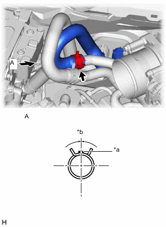
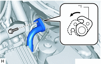
Text in Illustration *a for LHD: Brown Marking
for RHD: Purple Marking
*b 90° +/- 15° Connect the heater water inlet hose A (unit side) as shown in the illustration.
-
-
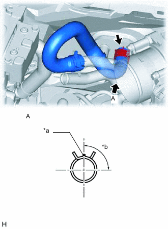
INSTALL HEATER WATER OUTLET HOSE A (for 2GR-FXE)
-
Text in Illustration *a for LHD: Blown Marking
for RHD: Purple Marking
*b 45°+/- 15° Connect the heater water outlet hose A (unit side) and attach the clip.
-
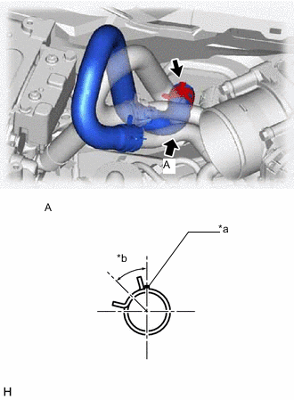
Text in Illustration *a Blue Marking *b 0°+/- 15° Connect the heater water outlet hose A (engine side) and attach the clip to install the heater water outlet hose A.
-
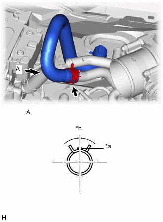
Text in Illustration *a Yellow Marking *b 0°+/- 15° Connect the heater water inlet hose A (engine side) and attach the clip to install the heater water inlet hose A.
-
Install the water hose set.
-
-
CONNECT HEATER WATER INLET HOSE A (for 2AR-FSE)
-
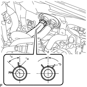
Text in Illustration *a Brown Marking 5 mm *b Brown Marking 2 mm *c 45° +/- 15° *d 0° +/- 15° Connect the heater water inlet hose A and attach the clip.
-
-
CONNECT HEATER WATER OUTLET HOSE A
-
Connect the heater water outlet hose A and attach the clip.
-
-
CONNECT AIR CONDITIONING TUBE ASSEMBLY
-
Remove the vinyl tape attached to the air conditioning tube assembly.
-
Sufficiently apply compressor oil to 2 new O-rings and the fitting surface of the air conditioning tube assembly.
Compressor oil ND-OIL 11 or equivalent -
Install the 2 O-rings to the air conditioning tube assembly.
-
Connect the air conditioning tube assembly.
Note
After the connection, check that the claw of the piping clamp is attached.
-
Text in Illustration *1 Plate Attach the plate as shown in the illustration and install the bolt.
- Torque:
- 9.8 N*m { 100 kgf*cm, 87 in.*lbf }
-
-
INSTALL FRONT WIPER MOTOR
-
CONNECT CABLE FROM NEGATIVE AUXILIARY BATTERY TERMINAL
Note
When disconnecting the cable, some systems need to be initialized after the cable is reconnected Click here.
-
INSTALL LUGGAGE COMPARTMENT TRIM COVER LH
-
INSTALL LUGGAGE COMPARTMENT FLOOR MAT
-
INSTALL AIR CLEANER CAP WITH AIR CLEANER HOSE (for 2GR-FXE)
-
ADD ENGINE COOLANT
-
for 2AR-FSE:
-
for 2GR-FXE:
-
-
CHARGE AIR CONDITIONING SYSTEM WITH REFRIGERANT
-
for HFC-134a(R134a):
-
for HFO-1234yf(R1234yf):
-
-
WARM UP COMPRESSOR
-
for HFC-134a(R134a):
-
for HFO-1234yf(R1234yf):
-
-
INSPECT FOR COOLANT LEAK
-
for 2AR-FSE:
-
for 2GR-FXE:
-
-
CHECK FOR REFRIGERANT GAS LEAK
-
for HFC-134a(R134a):
-
for HFO-1234yf(R1234yf):
-
-
INSTALL NO. 1 AIR CLEANER INLET
-
INSTALL ENGINE UNDER COVER
-
INSTALL V-BANK COVER SUB-ASSEMBLY (for 2GR-FXE)
-
INSTALL NO. 1 ENGINE COVER (for 2AR-FSE)
-
INSTALL COOL AIR INTAKE DUCT SEAL
-
INSTALL ENGINE ROOM SIDE COVER
-
CHECK SRS WARNING LIGHT