VEHICLE PROXIMITY NOTIFICATION SYSTEM There is No Sound Made
DESCRIPTION
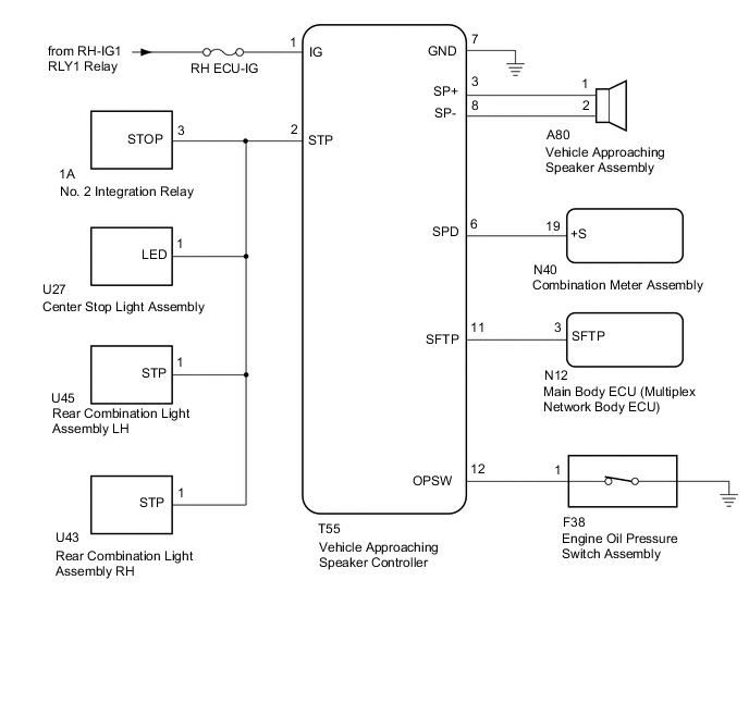
The vehicle approaching speaker controller receives stop light switch signals from the No. 2 integration relay, vehicle speed signals from the combination meter assembly, shift position P signals from the main body ECU (multiplex network body ECU) and engine operation signals from the engine oil pressure switch assembly in order to operate (sound) the vehicle approaching speaker assembly.
WIRING DIAGRAM
CAUTION / NOTICE / HINT
Note
-
Inspect the fuses and relays for circuits related to this system before performing the following inspection procedure.
-
The vehicle proximity notification system troubleshooting procedures are based on the premise that the following systems are operating normally. Check these systems first before troubleshooting the vehicle proximity notification system.
-
Meter/gauge system
-
Lighting system
-
Audio system
-
Navigation system
PROCEDURE
-
CHECK FOR DTC
-
Check for DTCs Click here.
Result Result Proceed to DTC B1350 is not output A DTC B1350 is output B GTS cannot communicate with the vehicle approaching warning system C
B 
GO TO DIAGNOSTIC TROUBLE CODE CHART (B1350) Click here
C
GO TO OTHER PROBLEM (The diagnostic tool cannot communicate with the vehicle approaching warning system) Click here
A 
-
-
PERFORM ACTIVE TEST USING GTS (PROXIMITY SOUND [VEHICLE STATIONARY])
-
Using the GTS, perform the Active Test Click here.
Vehicle Approaching Speaker Controller Tester Display Test Part Control Range Diagnostic Note Proximity Sound (Vehicle Stationary) Proximity sound (Vehicle stationary) ON / OFF Produces warning sound when vehicle is stopped OK The vehicle proximity notification system sounds or stops sounding according to the GTS display.
NG 
CHECK VEHICLE APPROACHING SPEAKER CONTROLLER (OUTPUT WAVEFORM) Click here
OK
-
-
READ VALUE USING GTS (STOP LIGHT SW)
-
Using the GTS, read the Data List Click here.
Vehicle Approaching Speaker Controller Tester Display Measurement Item/Range Normal Condition Diagnostic Note Stop Light SW State of brake pedal / OFF or ON OFF: Brake pedal released
ON: Brake pedal depressed
- OK GTS display changes according to the state of the brake pedal.
NG
CHECK STOP LIGHT OPERATION Click here
OK
-
-
READ VALUE USING GTS (VEHICLE SPEED)
-
Using the GTS, read the Data List Click here.
Vehicle Approaching Speaker Controller Tester Display Measurement Item/Range Normal Condition Diagnostic Note Vehicle Speed Vehicle speed / Min.: 0 km/h (0 mph), Max.: 255 km/h (158 mph) Almost same as actual vehicle speed - OK GTS display changes according to vehicle speed.
NG
CHECK HARNESS AND CONNECTOR (VEHICLE APPROACHING SPEAKER CONTROLLER - COMBINATION METER ASSEMBLY) Click here
OK
-
-
READ VALUE USING GTS (SHIFT POSITION)
-
Using the GTS, read the Data List Click here.
Vehicle Approaching Speaker Controller Tester Display Measurement Item/Range Normal Condition Diagnostic Note Shift Position Shift position P / Not Parking or Parking Not Parking: Shift lever not in P
Parking: Shift lever in P
- OK GTS display changes according to operation of the shift lever.
NG
CHECK VEHICLE APPROACHING SPEAKER CONTROLLER Click here
OK
-
-
READ VALUE USING GTS (OIL PRESSURE SW)
-
Using the GTS, read the Data List Click here.
Vehicle Approaching Speaker Controller Tester Display Measurement Item/Range Normal Condition Diagnostic Note Oil Pressure SW Engine oil pressure switch / OFF or ON OFF: Engine operate
ON: Engine not operate
- OK GTS display changes according to engine operation.
OK
REPLACE VEHICLE APPROACHING SPEAKER CONTROLLER Click here
NG
CHECK ENGINE OIL PRESSURE SWITCH ASSEMBLY (OPSW SIGNAL) Click here
-
-
CHECK VEHICLE APPROACHING SPEAKER CONTROLLER (OUTPUT WAVEFORM)
-
Disconnect the vehicle approaching speaker assembly connector.
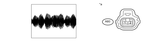
Text in Illustration *a Front view of wire harness connector
(to Vehicle Approaching Speaker Assembly)
- - -
Turn the power switch on (IG).
-
Using the GTS, perform the Active Test "Proximity Sound (Vehicle Stationary)" Click here.
Tech Tips
DTCs may be output when connectors are disconnected during inspection. Therefore, make sure to clear the DTCs using the GTS once the inspection has been completed.
-
Using an oscilloscope, check the waveform.
-
Check the signal waveform according to the condition(s) in the table below.
Item Condition Tester Connection A80-1 - A80-2 Tool Setting 1 V/DIV., 200 ms./DIV. Vehicle Condition Speaker operating
OK The waveform is displayed as shown in the illustration. -
NG
CHECK HARNESS AND CONNECTOR (VEHICLE APPROACHING SPEAKER CONTROLLER - VEHICLE APPROACHING SPEAKER ASSEMBLY) Click here
OK
-
-
INSPECT VEHICLE APPROACHING SPEAKER ASSEMBLY
Note
-
Make sure that there is no looseness, rattling, or other problem with the vehicle approaching speaker assembly installation.
-
Make sure that there is no foreign matter inside the vehicle approaching speaker assembly.
-
Remove the vehicle approaching speaker assembly Click here.
-
Inspect the vehicle approaching speaker assembly Click here.
OK
USE SIMULATION METHOD TO CHECK Click here
NG
REPLACE VEHICLE APPROACHING SPEAKER ASSEMBLY Click here
-
-
CHECK HARNESS AND CONNECTOR (VEHICLE APPROACHING SPEAKER CONTROLLER - VEHICLE APPROACHING SPEAKER ASSEMBLY)
-
Disconnect the T55 vehicle approaching speaker controller connector.
-
Disconnect the A80 vehicle approaching speaker assembly connector.
-
Measure the resistance according to the value(s) in the table below.
Standard Resistance Tester Connection Condition Specified Condition T55-3 (SP+) - A80-1 Always Below 1 Ω T55-8 (SP-) - A80-2 Always Below 1 Ω T55-3 (SP+) or A80-1 - Body ground Always 10 kΩ or higher T55-8 (SP-) or A80-2 - Body ground Always 10 kΩ or higher T55-3 (SP+) - T55-8 (SP-) Always 10 kΩ or higher
OK
REPLACE VEHICLE APPROACHING SPEAKER CONTROLLER Click here
NG
REPAIR OR REPLACE HARNESS OR CONNECTOR
-
-
CHECK STOP LIGHT OPERATION
-
Confirm that the stop lights illuminate properly Click here.
OK Stop lights illuminate properly.
NG
GO TO LIGHTING SYSTEM (EXT) Click here
OK
-
-
CHECK HARNESS AND CONNECTOR (VEHICLE APPROACHING SPEAKER CONTROLLER - NO. 2 INTEGRATION RELAY)
-
Disconnect the T55 vehicle approaching speaker controller connector.
-
Disconnect the 1A No. 2 integration relay connector.
-
Disconnect the U27 center stop light assembly connector.
-
Disconnect the U45 rear combination light assembly LH connector.
-
Disconnect the U43 rear combination light assembly RH connector.
-
Measure the resistance according to the value(s) in the table below.
Standard Resistance Tester Connection Condition Specified Condition T55-2 (STP) - 1A-3 (STOP) Always Below 1 Ω T55-2 (STP) or 1A-3 (STOP) - Body ground Always 10 kΩ or higher
OK
REPLACE VEHICLE APPROACHING SPEAKER CONTROLLER Click here
NG
REPAIR OR REPLACE HARNESS OR CONNECTOR
-
-
CHECK HARNESS AND CONNECTOR (VEHICLE APPROACHING SPEAKER CONTROLLER - COMBINATION METER ASSEMBLY)
-
Disconnect the T55 vehicle approaching speaker controller connector.
-
Disconnect the N40 combination meter assembly connector.
-
Measure the resistance according to the value(s) in the table below.
Standard Resistance Tester Connection Condition Specified Condition T55-6 (SPD) - N40-19 (+S) Always Below 1 Ω T55-6 (SPD) or N40-19 (+S) - Body ground Always 10 kΩ or higher
NG
REPAIR OR REPLACE HARNESS OR CONNECTOR
OK
-
-
CHECK COMBINATION METER ASSEMBLY (OUTPUT WAVEFORM)
-
With the connector of the combination meter assembly connected, check the waveform Click here.
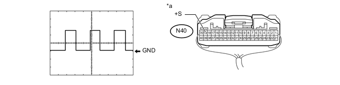
Text in Illustration *a Component with harness connected
(Combination Meter Assembly)
- - -
Using an oscilloscope, check the waveform.
-
Check the signal waveform according to the condition(s) in the table below.
Item Condition Tester Connection N40-19 (+S) - Body ground Tool Setting 5 V/DIV., 20 ms./DIV. Vehicle Condition Driving at approximately 20 km/h (12 mph) OK The waveform is displayed as shown in the illustration.
-
OK
REPLACE VEHICLE APPROACHING SPEAKER CONTROLLER Click here
NG
GO TO METER / GAUGE SYSTEM Click here
-
-
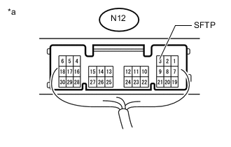
CHECK VEHICLE APPROACHING SPEAKER CONTROLLER
-
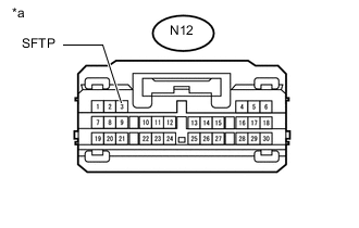
Text in Illustration *a Front view of wire harness connector
(to Main Body ECU [Multiplex Network Body ECU])
Disconnect the main body ECU (multiplex network body ECU) connector.
-
Measure the voltage according to the value (s) in the table below.
Standard Voltage Tester Connection Condition Specified Condition N12-3 (SFTP) - Body ground Power switch on (IG) 11 to 14 V Power switch off Below 1 V
NG
CHECK HARNESS AND CONNECTOR (VEHICLE APPROACHING SPEAKER CONTROLLER - MAIN BODY ECU [MULTIPLEX NETWORK BODY ECU]) Click here
OK
-
-
CHECK MAIN BODY ECU (MULTIPLEX NETWORK BODY ECU) (SFTP SIGNAL)
-
Text in Illustration *a Component with harness connected
(Main Body ECU [Multiplex Network Body ECU])
With the connector of the main body ECU (multiplex network body ECU) connector Click here.
-
Measure the voltage according to the value (s) in the table below.
Standard Voltage Tester Connection Condition Specified Condition N12-3 (SFTP) - Body ground Power switch on (IG), Shift lever in P Below 2.5 V Power switch on (IG), Shift lever not in P 8 V or higher
OK
REPLACE VEHICLE APPROACHING SPEAKER CONTROLLER Click here
NG
REPLACE MAIN BODY ECU (MULTIPLEX NETWORK BODY ECU) Click here
-
-
CHECK HARNESS AND CONNECTOR (VEHICLE APPROACHING SPEAKER CONTROLLER - MAIN BODY ECU [MULTIPLEX NETWORK BODY ECU])
-
Disconnect the T55 vehicle approaching speaker controller connector.
-
Disconnect the N12 main body ECU (multiplex network body ECU) connector.
-
Measure the resistance according to the value(s) in the table below.
Standard Resistance Tester Connection Condition Specified Condition T55-11 (SFTP) - N12-3 (SFTP) Always Below 1 Ω T55-11 (SFTP) or N12-3 (SFTP) - Body ground Always 10 kΩ or higher
OK
REPLACE VEHICLE APPROACHING SPEAKER CONTROLLER Click here
NG
REPAIR OR REPLACE HARNESS OR CONNECTOR
-
-
CHECK ENGINE OIL PRESSURE SWITCH ASSEMBLY (OPSW SIGNAL)
-
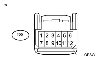
Text in Illustration *a Front view of wire harness connector
(to Vehicle Approaching Speaker Controller)
Disconnect the vehicle approaching speaker controller connector.
-
Measure the voltage according to the value(s) in the table below.
Standard Voltage Tester Connection Condition Specified Condition T55-12 (OPSW) - Switch body Idling* 8 V or higher Power switch on (IG) Below 2.0 V *: Enter vehicle preparation mode, and then perform the inspection Click here.
OK
REPLACE VEHICLE APPROACHING SPEAKER CONTROLLER Click here
NG
-
-
CHECK HARNESS AND CONNECTOR (VEHICLE APPROACHING SPEAKER CONTROLLER - ENGINE OIL PRESSURE SWITCH ASSEMBLY)
-
Disconnect the T55 vehicle approaching speaker controller connector.
-
Disconnect the F38 engine oil pressure switch assembly connector.
-
Measure the resistance according to the value (s) in the table below.
Standard Resistance Tester Connection Condition Specified Condition T55-12 (OPSW) - F38-1 Always Below 1 Ω T55-12 (OPSW) or F38-1 - Body ground Always 10 kΩ or higher
OK
REPLACE ENGINE OIL PRESSURE SWITCH ASSEMBLY Click here
NG
REPAIR OR REPLACE HARNESS OR CONNECTOR
-