VEHICLE PROXIMITY NOTIFICATION SYSTEM TERMINALS OF ECU
-
CHECK VEHICLE APPROACHING SPEAKER CONTROLLER
-
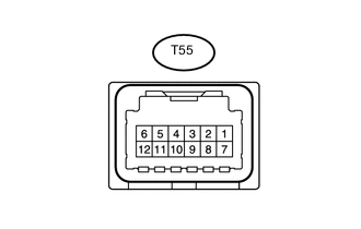
Disconnect the T55 vehicle approaching speaker controller connector.
-
Measure the voltage and resistance according to the value(s) in the table below.
Terminal No. Wiring Color Terminal Description Condition Specified Condition T55-1 (IG) - Body ground L - Body ground IG power supply Power switch on (IG) 11 to 14 V Power switch off Below 1 V T55-7 (GND) - Body ground W-B - Body ground Ground Always Below 1 Ω -
Reconnect the T55 vehicle approaching speaker controller connector.
-
Measure the voltage and waveform according to the value(s) in the table below.
Terminal No. (Symbol) Wiring Color Terminal Description Condition Specified Condition T55-2 (STP) - T55-7 (GND) R - W-B Stop light switch signal input Brake pedal depressed 8 V or higher Brake pedal released Below 1 V T55-3 (SP+) - T55-8 (SP-) V - Y Vehicle approaching speaker signal output Driving in EV drive mode at approximately 20 km/h (12 mph) or less
(Vehicle approaching speaker operating)
A waveform synchronized with the sound is output. T55-5 (SW) - T55-7 (GND) P - W-B Integration control and panel assembly (vehicle approaching speaker switch) signal Power switch on (IG), integration control and panel assembly (vehicle approaching speaker switch) on 6 V or higher Power switch on (IG), integration control and panel assembly (vehicle approaching speaker switch) off Below 1 V T55-6 (SPD) - T55-7 (GND) SB - W-B Speed signal input Driving at approximately 20 km/h (12 mph) Pulse generation
(See Waveform 1)
T55-9 (PRST) - T55-7 (GND) L - W-B SIL communication signal Power switch on (IG), during transmission Pulse generation
(See Waveform 2)
T55-10 (IND) - T55-7 (GND) B - W-B Integration control and panel assembly (vehicle approaching speaker switch) indicator signal Power switch on (IG), integration control and panel assembly (vehicle approaching speaker switch) on Below 2.8 V Power switch on (IG), integration control and panel assembly (vehicle approaching speaker switch) off 11 to 14 V T55-11 (SFTP) - T55-7 (GND) Y - W-B Shift lever position sensor signal input Power switch on (IG), Shift lever in P Below 2.5 V Power switch on (IG), Shift lever not in P 8 V or higher T55-12 (OPSW) - T55-7 (GND) L - W-B Engine oil pressure switch signal input Power switch on (Ready), engine stopped Below 2.0 V Power switch on (Ready), engine running 8 V or higher
-
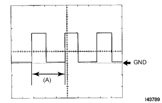
Waveform 1 (Reference):
Item Condition Tester Connection T55-6 (SPD) - T55-7 (GND) Tool Setting 5 V/DIV., 20 ms./DIV. Vehicle Condition Driving at approximately 20 km/h (12 mph) Tech Tips
If the vehicle speed increases, width (A) becomes narrower.
-
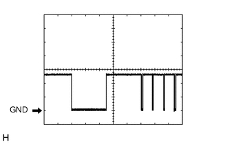
Waveform 2 (Reference):
Item Condition Tester Connection T55-9 (PRST) - T55-7 (GND) Tool Setting 5 V/DIV., 10 ms./DIV. Vehicle Condition Power switch on (IG), during transmission
-
-
-
CHECK MAIN BODY ECU (MULTIPLEX NETWORK BODY ECU) AND COWL SIDE JUNCTION BLOCK LH
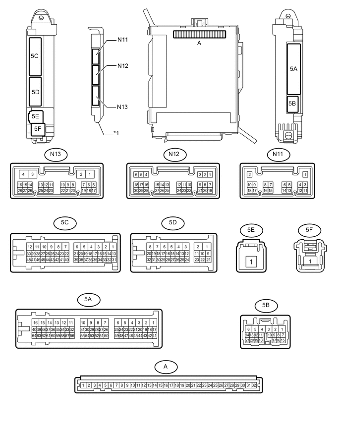
Text in Illustration *1 Main Body ECU (Multiplex Network Body ECU) - -
-
Remove the main body ECU from the cowl side junction block LH Click here.
-
Connect the cowl side junction block LH connectors.
-
Measure the resistance and voltage according to the value(s) in the table below.
Terminal No. (Symbol) Wiring Color Terminal Description Condition Specified Condition A-32 (IG) - Body ground - Ignition power supply Power switch on (IG) 11 to 14 V Power switch off Below 1 V A-30 (BECU) - Body ground - Battery power supply Always 11 to 14 V A-29 (ACC) - Body ground - ACC power supply Power switch on (ACC) 11 to 14 V Power switch off Below 1 V A-11 (GND1) - Body ground - Ground Always Below 1 Ω -
Install the main body ECU Click here.
-
Measure the voltage according to the value(s) in the table below.
Terminal No. (Symbol) Wiring Color Terminal Description Condition Specified Condition N12-3 (SFTP) - Body ground B - Body ground Shift position P signal Power switch on (IG), Shift lever in P Below 2.5 V Power switch on (IG), Shift lever not in P 8 V or higher
-