WATER PUMP INSTALLATION
PROCEDURE
-
INSTALL WATER PUMP ASSEMBLY
-
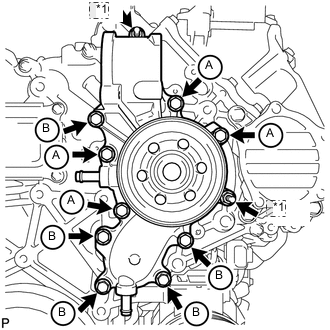
*1 Nut Temporarily install a new gasket and the water pump with the 9 bolts and 2 nuts.
Bolt Length Item Length Bolt A 30 mm (1.18 in.) Bolt B 80 mm (3.15 in.) -
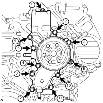
Uniformly tighten the 9 bolts and 2 nuts of the water pump in the order shown in the illustration.
- Torque:
- 25 N*m { 250 kgf*cm, 18 ft.*lbf }
Note
After installing all of the bolts and nuts, check that all of the bolts and nuts are tightened to the torque specification.
-
-
INSTALL WATER OUTLET
-
Connect the water outlet to the No. 2 water hose joint, and install a new gasket and the water outlet with the 2 bolts.
- Torque:
- 21 N*m { 214 kgf*cm, 15 ft.*lbf }
-
-
INSTALL FAN BRACKET SUB-ASSEMBLY
-
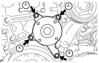
Install the fan bracket with the 4 bolts.
- Torque:
- 21 N*m { 214 kgf*cm, 15 ft.*lbf }
Bolt Length Item Length Bolt A 30 mm (1.18 in.) Bolt B 80 mm (3.15 in.)
-
-
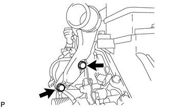
INSTALL NO. 1 OIL COOLER HOSE
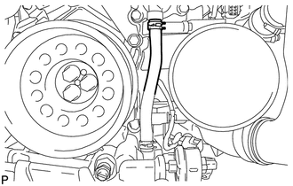
Note
Make sure that there is clearance between the oil cooler hose and crankshaft pulley.
-
INSTALL NO. 2 IDLER PULLEY BRACKET (w/ Viscous Heater)
-
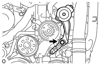
Temporarily install the No. 2 idler pulley bracket with the bolt.
-
Temporarily install the 2 bolts to the No. 2 idler pulley bracket bolt hole.
-
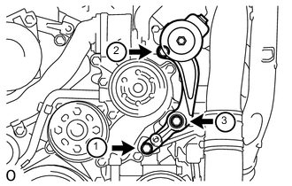
Uniformly tighten the 3 bolts of the No. 2 idler pulley bracket in the order shown in the illustration.
- Torque:
- 49 N*m { 495 kgf*cm, 36 ft.*lbf }
-
-
INSTALL NO. 2 IDLER PULLEY (w/ Viscous Heater)
-
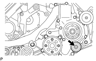
Install the collar, No. 2 idler pulley and cover with the bolt.
- Torque:
- 49 N*m { 495 kgf*cm, 36 ft.*lbf }
-
-
INSTALL THERMOSTAT
-
INSTALL WATER INLET
-
INSTALL NO. 1 IDLER PULLEY BRACKET (w/ Viscous Heater)
-
INSTALL VISCOUS WITH MAGNET CLUTCH HEATER ASSEMBLY (w/ Viscous Heater)
-
INSTALL HEATER WATER PIPE SUB-ASSEMBLY (w/ Viscous Heater)
-
INSTALL FAN PULLEY
-
INSTALL FAN SHROUD WITH FAN
-
INSTALL OIL COOLER TUBE (for Automatic Transmission)
-
INSTALL V-RIBBED BELT
-
INSTALL NO. 3 IDLER PULLEY (w/ Viscous Heater)
-
INSTALL NO. 1 IDLER PULLEY (w/ Viscous Heater)
-
INSTALL V-RIBBED BELT (w/ Viscous Heater)
-
CONNECT NO. 2 RADIATOR HOSE
-
CONNECT NO. 1 RADIATOR HOSE
-
INSTALL VANE PUMP ASSEMBLY
-
INSTALL RADIATOR RESERVOIR ASSEMBLY
-
INSTALL NO. 1 OIL RESERVOIR BRACKET
-
INSTALL VANE PUMP OIL RESERVOIR ASSEMBLY
-
INSTALL INTAKE AIR CONNECTOR
-
TEMPORARILY INSTALL NO. 1 AIR CLEANER HOSE
-
INSTALL AIR CLEANER CAP SUB-ASSEMBLY
-
INSTALL NO. 1 ENGINE COVER SUB-ASSEMBLY (w/ Intercooler)
-
INSTALL NO. 3 ENGINE ROOM WIRE
-
CONNECT CABLE TO NEGATIVE BATTERY TERMINAL
Note
When disconnecting the cable, some systems need to be initialized after the cable is reconnected Click here.
-
Connect the cables to negative (-) main battery and sub-battery terminals.
-
-
ADD ENGINE COOLANT
-
INSPECT FOR ENGINE COOLANT LEAK
-
INSTALL UPPER RADIATOR SUPPORT SEAL
-
INSTALL NO. 1 ENGINE UNDER COVER SUB-ASSEMBLY
-
INSTALL FRONT FENDER SPLASH SHIELD SUB-ASSEMBLY RH
-
INSTALL FRONT FENDER SPLASH SHIELD SUB-ASSEMBLY LH
-
INSTALL FRONT FENDER APRON SEAL FRONT RH
-
INSTALL FRONT WHEEL RH