AIR CONDITIONING UNIT REMOVAL
PROCEDURE
-
RECOVER REFRIGERANT FROM AIR CONDITIONING SYSTEM (for HFC-134a(R134a))
-
RECOVER REFRIGERANT FROM AIR CONDITIONING SYSTEM (for HFO-1234yf(R1234yf))
-
REMOVE WINDSHIELD WIPER MOTOR AND LINK ASSEMBLY (for RHD)
-
REMOVE NO. 1 HEATER AIR DUCT SPLASH SHIELD SEAL (for RHD)
-
REMOVE NO. 2 HEATER AIR DUCT SPLASH SHIELD SEAL (for RHD)
-
REMOVE COWL BODY MOUNTING REINFORCEMENT RH (for RHD)
-
REMOVE OUTER COWL TOP PANEL SUB-ASSEMBLY (for RHD)
-
SEPARATE RESERVOIR TUBE ASSEMBLY (for RHD)
-
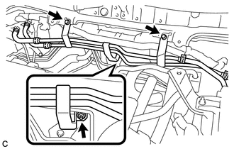
Remove the 2 bolts, nut and separate the reservoir tube assembly.
-
-
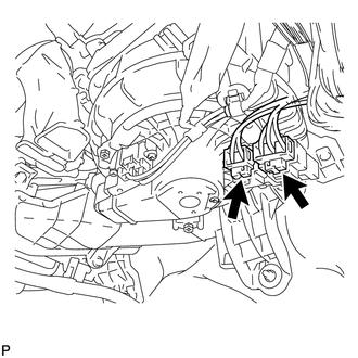
DISCONNECT SUCTION PIPE SUB-ASSEMBLY
-
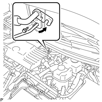
Remove the bolt and slide the hook connector.
-
Disconnect the suction pipe sub-assembly.
-
Remove the O-ring from the suction pipe sub-assembly.
Note
Seal the openings of the disconnected parts using vinyl tape to prevent entry of moisture and foreign matter.
-
-
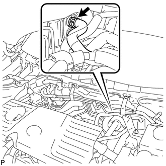
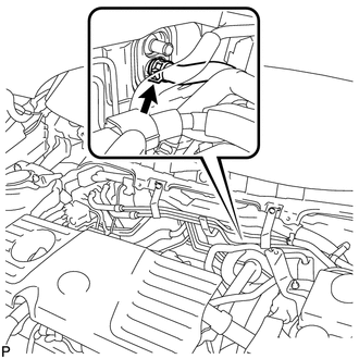
DISCONNECT AIR CONDITIONING TUBE AND ACCESSORY ASSEMBLY
-
Disconnect the air conditioning tube and accessory assembly.
-
Remove the O-ring from the air conditioning tube and accessory assembly.
Note
Seal the openings of the disconnected parts using vinyl tape to prevent entry of moisture and foreign matter.
-
-
DISCONNECT OUTLET HEATER WATER HOSE
-
Using pliers, grip the claws of the clip and slide the clip to disconnect the outlet heater water hose.
Note
-
Do not apply excessive force to the heater water hose.
-
Prepare a drain pan or cloth in case the coolant leaks.
-
-
-
DISCONNECT INLET HEATER WATER HOSE
-
Using pliers, grip the claws of the clip and slide the clip to disconnect the inlet heater water hose.
Note
-
Do not apply excessive force to the inlet heater water hose.
-
Prepare a drain pan or cloth in case the coolant leaks.
-
-
-
REMOVE LOWER INSTRUMENT PANEL SUB-ASSEMBLY
-
REMOVE POWER STEERING ECU ASSEMBLY (for LHD)
-
REMOVE POWER STEERING ECU ASSEMBLY (for RHD)
-
REMOVE STEERING POST ASSEMBLY
-
REMOVE WINDSHIELD WIPER RELAY ASSEMBLY
-
REMOVE CENTER INSTRUMENT PANEL REINFORCEMENT SUB-ASSEMBLY
-
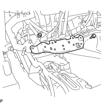
Remove the bolt, nut and center instrument panel reinforcement sub-assembly.
-
-
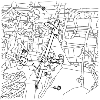
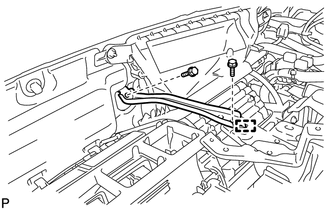
REMOVE NO. 1 INSTRUMENT PANEL BRACE SUB-ASSEMBLY
-
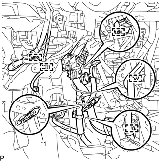
Text in Illustration *1 Earth Wire Disengage each clamp.
-
Remove the bolt and disconnect the earth wire.
-
Remove the screw.
-
Remove the bolt, nut and No. 1 instrument panel brace sub-assembly.
-
-
REMOVE NO. 2 INSTRUMENT PANEL BRACE SUB-ASSEMBLY
-
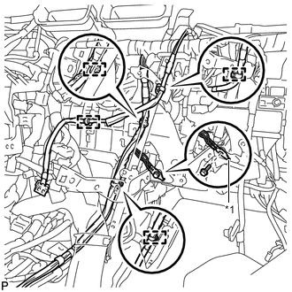
Text in Illustration *1 Earth Wire Disengage each clamp.
-
Remove the bolt and disconnect the earth wire.
-
Remove the screw.
-
Remove the bolt, nut and No. 2 instrument panel brace sub-assembly.
-
-
REMOVE REAR NO. 2 AIR DUCT
-
Disengage the 6 claws and remove the rear No. 2 air duct.
-
-
REMOVE REAR NO. 1 AIR DUCT
-
Disengage the 4 claws and remove the rear No. 1 air duct.
-
-
REMOVE NO. 2 HEATER TO REGISTER DUCT
-
Remove the 3 clips and No. 2 heater to register duct.
-
-
REMOVE LOWER DEFROSTER NOZZLE ASSEMBLY
-
for RHD:
-
Disengage each clamp.
-
-
Remove the 2 clips.
-
Disengage the 6 claws and remove the lower defroster nozzle assembly.
-
-
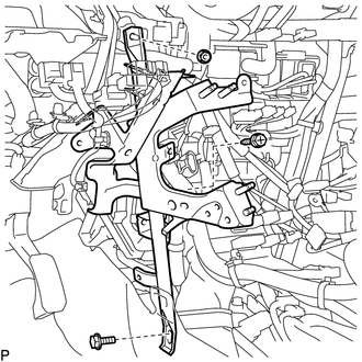
REMOVE CENTER INSTRUMENT PANEL TO COWL BRACE
-
Remove the 2 bolts.
-
Disengage the guide and remove the instrument panel reinforcement.
-
-
REMOVE INSTRUMENT PANEL JUNCTION BLOCK ASSEMBLY (for LHD)
-
REMOVE INSTRUMENT PANEL JUNCTION BLOCK ASSEMBLY (for RHD)
-
REMOVE ECU INTEGRATION BOX RH (for LHD)
-
REMOVE ECU INTEGRATION BOX LH (for RHD)
-
REMOVE ECU INTEGRATION BOX RH (for RHD)
-
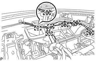
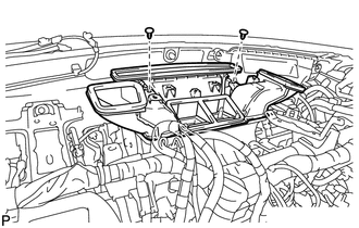
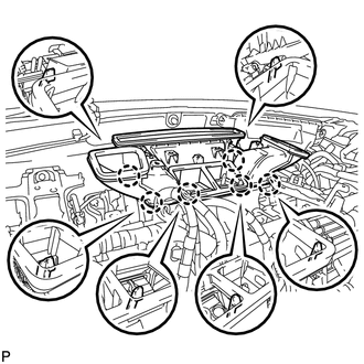
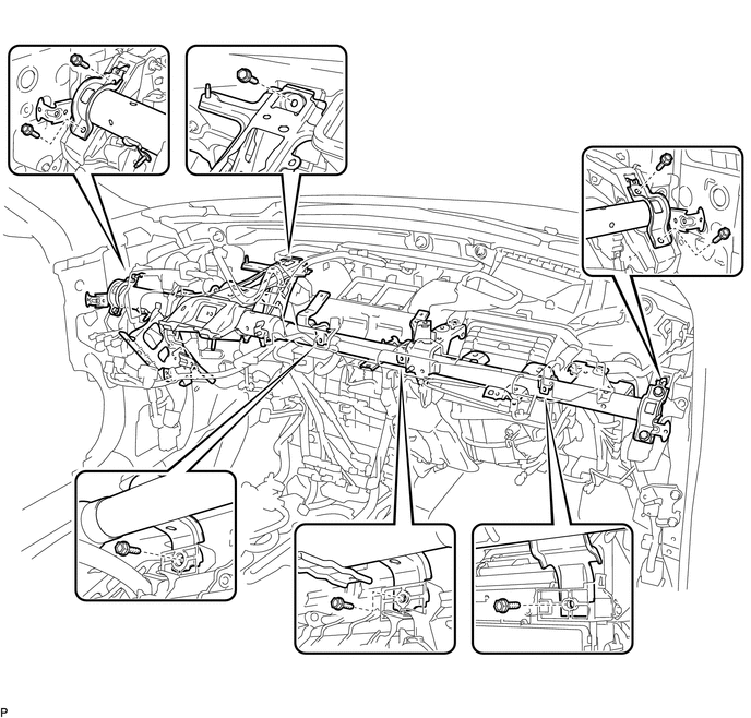
REMOVE INSTRUMENT PANEL REINFORCEMENT
-
w/ PTC Heater:
-
Disconnect the 2 connectors.
-
-
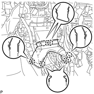
for LHD:
-
Disconnect the center airbag sensor connectors from the center airbag sensor assembly as shown in the illustration.
Note
When disconnecting any airbag connector, take care not to damage the airbag wire harness.
-
Remove the 2 bolts and disconnect the 2 earth wires.
-
Remove the 2 bolts.
-
Disconnect each connector.
-
Disengage each clamp.
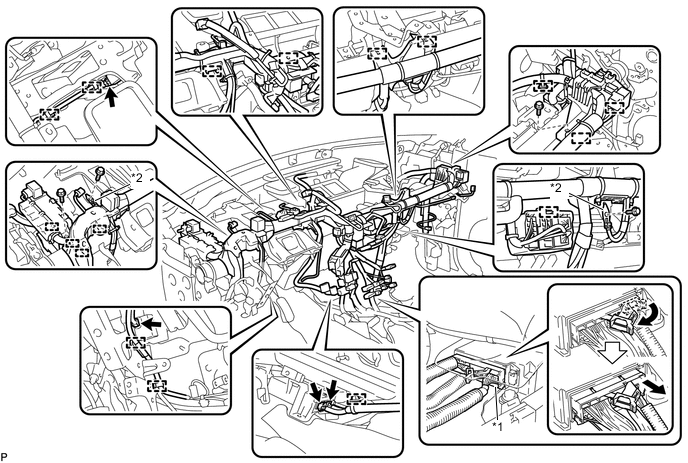
Text in Illustration *1 Center Airbag Sensor Connector *2 Earth wire
-
-
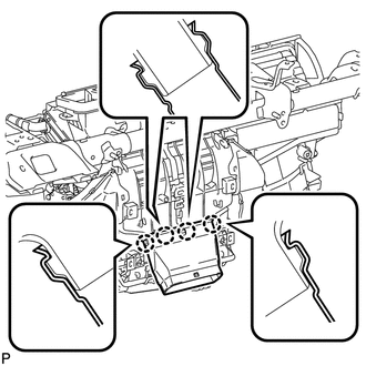
for RHD:
-
Disconnect the center airbag sensor connectors from the center airbag sensor assembly as shown in the illustration.
Note
When disconnecting any airbag connector, take care not to damage the airbag wire harness.
-
Remove the 2 bolts and disconnect the 2 earth wires.
-
Remove the 3 bolts.
-
Disconnect each connector.
-
Disengage each clamp.
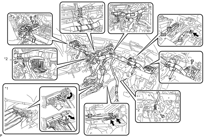
Text in Illustration *1 Center Airbag Sensor Connector *2 Earth wire
-
-
for LHD:
-
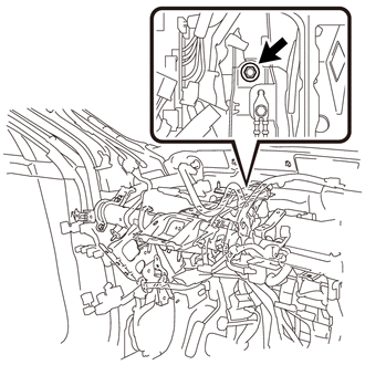
Remove the bolt and separate the brake pedal support assembly from the instrument panel reinforcement.
-
-
Remove the 8 bolts and instrument panel reinforcement.
-
-
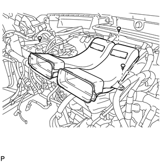
REMOVE AIR CONDITIONING UNIT ASSEMBLY
Note
-
Be sure to support the air conditioning unit assembly when removing it because failure to do so may cause brackets of the air conditioning unit assembly to break.
-
When disassembling the air conditioning unit, eliminate static electricity by touching the vehicle body to prevent electrical components from being damaged.
-
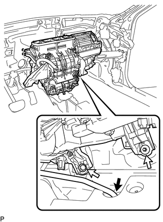
Disconnect the drain cooler hose.
-
Remove the bolt, nut and air conditioning unit assembly.
-