BACK WINDOW GLASS INSTALLATION
CAUTION / NOTICE / HINT
Note
Make sure to use Toyota Genuine Windshield Glass Adhesive (High Modulus Type) or an equivalent high modulus adhesive.
PROCEDURE
-
INSTALL BACK WINDOW GLASS DAM
-
Apply Primer G to the installation part of the window glass dam.
Note
-
Allow the primer to dry for 3 minutes or more.
-
Throw away any leftover primer.
-
Do not apply too much primer.
-
-
Remove the peeling paper from the adhesive part of the dam. Install the dam (adhesive side) to the glass (Primer G area) as shown in the illustration.
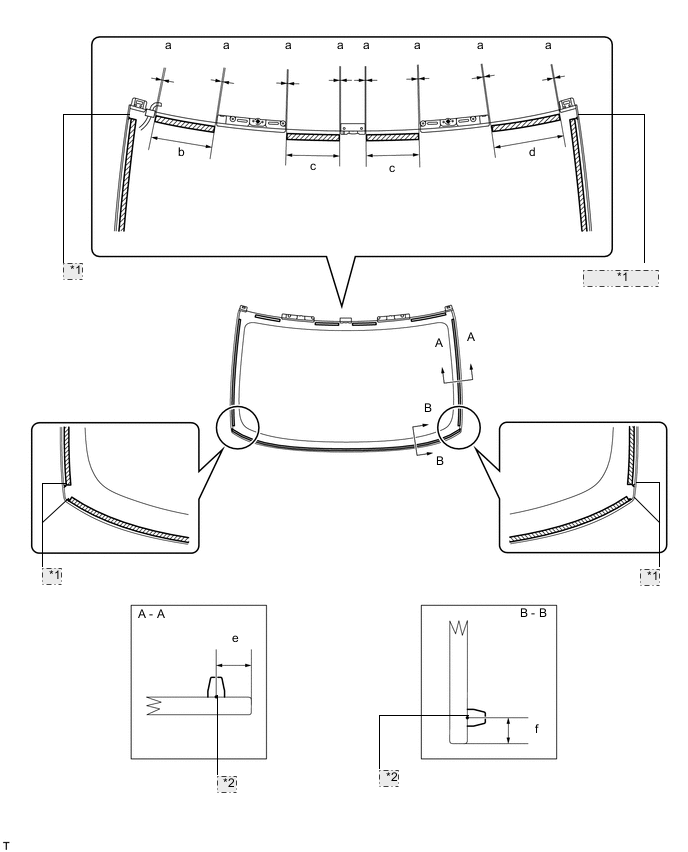
Backside *1 Ceramic Notch *2 Dam Center Line 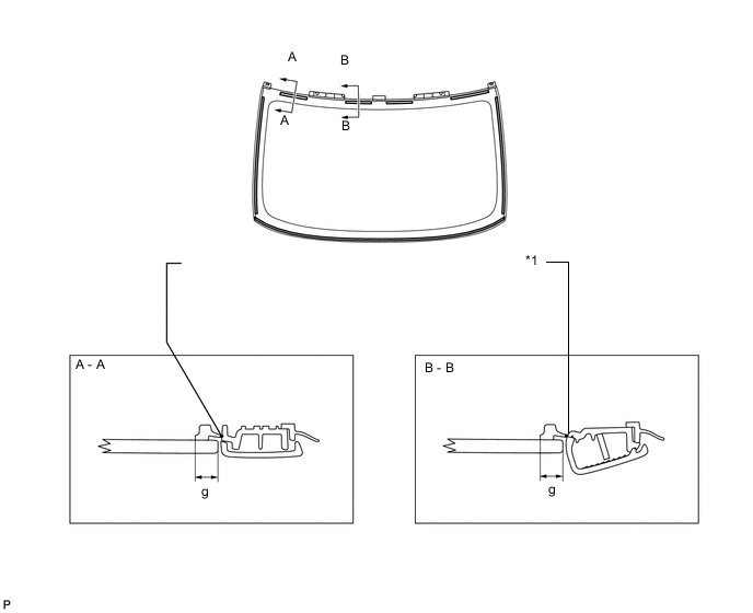
Backside *1 Attach the dam using the center stop light as a guide. Tech Tips
Attach the dam using the center stop light as a guide.
Standard measurement Area Specified Condition a 1.0 mm (0.039 in.) or less b 159.0 mm (6.259 in.) c 146.0 mm (5.748 in.) d 192.0 mm (7.559 in.) e 9.5 mm (0.377 in.) f 7.5 mm (0.295 in.) g (Reference) 8.0 mm (0.315 in.)
-
-
INSTALL BACK WINDOW GLASS

*1 CORRECT *2 Primer M *3 Adhesive *4 INCORRECT
-
Using a brush or sponge, apply Primer M to the exposed part of the vehicle body.
Note
-
Allow the primer to dry for 3 minutes or more.
-
Do not apply primer to the adhesive.
-
Throw away any leftover primer.
-
Do not apply too much primer.
-
-
Using a brush or sponge, apply Primer G to the contact surface of the back window glass.
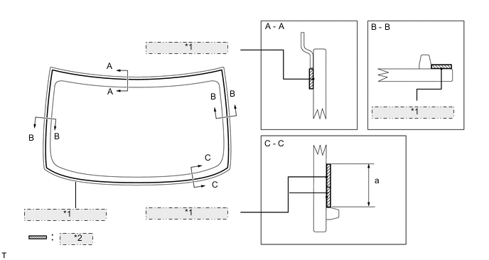
Backside *1 Adhesive Center Line *2 Primer G Standard measurement Area Specified Condition a 19.0 mm (0.748 in.) Tech Tips
If primer is applied to an area that is not specified, wipe off the primer with a non-residue solvent before it dries.
Note
-
Allow the primer to dry for 3 minutes or more.
-
Throw away any leftover primer.
-
Do not apply too much primer.
-
-
Apply adhesive to the back window glass.
Adhesive Toyota Genuine Windshield Glass Adhesive (High modulus Type) or Equivalent
-
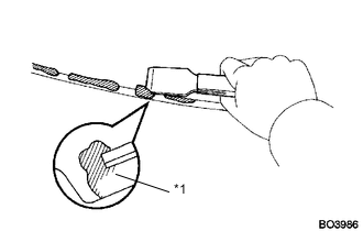
Cut off the tip of the cartridge nozzle as shown in the illustration below.
Tech Tips
After cutting off the tip, use all adhesive within the time frame written in the table below.
Usage time frame Temperature Usage Time Frame 35°C (95°F) 15 minutes 20°C (68°F) 1 hour 40 minutes 5°C (41°F) 8 hours -
Load the sealer gun with the cartridge.
-
Apply adhesive to the back window glass as shown in the illustration.
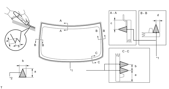
Backside *1 Adhesive Center Line *2 Adhesive Standard measurement Area Specified Condition a 12.0 mm (0.472 in.) b 8.0 mm (0.315 in.) c 12.1 mm (0.476 in.) d 3.0 mm (0.118 in.) e 14 mm (0.551 in.)
-
-
Install the back window glass to the vehicle body.
-
Hold the back window glass securely in place with tape or equivalent until the adhesive has hardened.
Note
-
Allow the primer coating to dry for 3 minutes or more.
-
Check that the clips are attached to the vehicle body correctly.
-
Check the clearance between the vehicle body and glass.
-
-
Lightly press the front surface of the back window glass to ensure that the back window glass is securely fit to the vehicle body.
-
*1 Adhesive Using a scraper, remove any excess or protruding adhesive.
Tech Tips
Apply adhesive onto the glass rim.
Note
Do not drive the vehicle within the time written in the table below.
Minimum time Temperature Minimum time prior to driving vehicle 35°C (95°F) 1 hour 30 minutes 20°C (68°F) 5 hours 5°C (41°F) 24 hours -
Install the defogger wire with the nut and 2 clamps.
-
Connect the 2 connectors.
-
-
-
CHECK FOR LEAKS AND REPAIR
-
Conduct a leak test after the adhesive has completely hardened.
-
Seal any leaks with auto glass sealer.
-
-
INSTALL CENTER STOP LIGHT ASSEMBLY
-
INSTALL CENTER STOP LIGHT CLIP
-
INSTALL CENTER STOP LIGHT COVER
-
INSTALL NO. 2 CENTER STOP LIGHT COVER
-
INSTALL LUGGAGE COMPARTMENT DOOR HINGE COVER LH
-
Clean the vehicle body surface.
-
Using a heat light, heat the vehicle body surface.
-
Remove the double-sided tape from the vehicle body.
-
Wipe off any tape adhesive residue with cleaner.
-
-
Install the moulding.
-
Using a heat light, heat the vehicle body and moulding.
-
Remove the peeling paper from the face of the moulding.
Tech Tips
After removing the peeling paper, keep the exposed adhesive free from foreign matter.
-
-
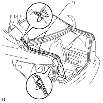
*1 Doudle-sided Tape Attach the 2 clips to install the a new moulding.
-
-
INSTALL LUGGAGE COMPARTMENT DOOR HINGE COVER RH
Tech Tips
Use the same procedures described for the LH side.
-
INSTALL REAR COMBINATION LIGHT ASSEMBLY LH
-
INSTALL REAR COMBINATION LIGHT ASSEMBLY RH
Tech Tips
Use the same procedure described for the LH side.
-
INSTALL LUGGAGE COMPARTMENT TRIM COVER ASSEMBLY LH
-
INSTALL LUGGAGE COMPARTMENT TRIM COVER ASSEMBLY RH
-
INSTALL BACK WINDOW MOULDING OUTSIDE LOWER
-
Clean the vehicle body surface.
-
Using a heat light, heat the vehicle body surface.
-
Remove the double-sided tape from the vehicle body.
-
Wipe off any tape adhesive residue with cleaner.
-
-
Install the moulding.
-
Using a heat light, heat the moulding.
-
Remove the peeling paper from the face of the moulding.
Tech Tips
After removing the peeling paper, keep the exposed adhesive free from foreign matter.
-
-
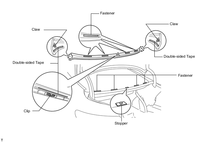
Attach the clip on the center of the moulding. Use the stoppers (left and right setting stoppers) on the bottom edge of the back window glass to determine the moulding's orientation. Then attach the 2 claws and 4 fasteners to install the a new moulding.
Tech Tips
As the stoppers on the bottom edge of the glass are only for determining the moulding's position, they do not attach to the moulding.
-
-
INSTALL REAR FLOOR FINISH PLATE
-
INSTALL FRONT LUGGAGE COMPARTMENT TRIM COVER
-
INSTALL LUGGAGE COMPARTMENT NO. 2 TRIM HOOK (w/o Rear Cooler)
-
INSTALL LUGGAGE COMPARTMENT NO. 1 LIGHT ASSEMBLY
-
INSTALL DECK TRIM SIDE BOARD LH
-
INSTALL DECK TRIM SIDE BOARD RH
-
INSTALL ROPE HOOK ASSEMBLY
-
INSTALL ROPE HOOK
-
INSTALL LUGGAGE COMPARTMENT MAT SUB-ASSEMBLY
-
INSTALL ROOF NO. 1 DRIP SIDE FINISH MOULDING CLIP
-
INSTALL NO. 3 WINDSHIELD OUTSIDE MOULDING CLIP
-
INSTALL ROOF NO. 2 DRIP SIDE FINISH MOULDING CLIP
-
INSTALL NO. 2 WINDSHIELD OUTSIDE MOULDING CLIP
-
INSTALL NO. 1 WINDSHIELD OUTSIDE MOULDING CLIP
Tech Tips
Use the same procedures described for the No. 2 clip.
-
INSTALL ROOF DRIP SIDE FINISH MOULDING CENTER LH
-
INSTALL ROOF DRIP SIDE FINISH MOULDING CENTER RH
Tech Tips
Use the same procedures described for the LH side.
-
INSTALL FRONT FENDER TO COWL SIDE SEAL LH
-
INSTALL FRONT FENDER TO COWL SIDE SEAL RH
Tech Tips
Use the same procedure described for the LH side.
-
INSTALL AMPLIFIER ANTENNA ASSEMBLY
-
INSTALL ROOF HEADLINING ASSEMBLY
-
Return the roof headlining to its original position.
For Standard Body, refer to the following procedures ( Click here).
For Long Body, refer to the following procedures ( Click here).
-
-
INSTALL ASSIST GRIP SUB-ASSEMBLY
-
INSTALL ROOF SIDE REGISTER BEZEL LH (w/ Rear Cooler)
-
INSTALL ROOF SIDE REGISTER BEZEL RH (w/ Rear Cooler)
-
INSTALL COAT HOOK
-
INSTALL REAR VANITY LIGHT ASSEMBLY
-
INSTALL SPOT LIGHT ASSEMBLY
-
INSTALL ROOF CONSOLE BOX ASSEMBLY (w/ Rear Seat Entertainment System)
-
INSTALL NO. 2 PACKAGE TRAY TRIM PANEL ASSEMBLY
-
INSTALL PACKAGE TRAY TRIM PANEL ASSEMBLY
-
INSTALL ROOF SIDE GARNISH INNER LH
-
INSTALL ROOF SIDE GARNISH INNER RH
-
INSTALL REAR SEAT SIDE GARNISH LH
-
INSTALL REAR SEAT SIDE GARNISH RH
-
INSTALL REAR DOOR SCUFF PLATE LH
-
for Standard Body:
Install the rear door scuff plate Click here.
-
for Long Body:
Install the rear door scuff plate Click here.
-
-
INSTALL REAR DOOR SCUFF PLATE RH
-
for Standard Body:
Install the rear door scuff plate Click here.
-
for Long Body:
Install the rear door scuff plate Click here.
-
-
INSTALL REAR SEAT ASSEMBLY
-
for Power Seat:
Install the rear seat Click here.
-
for Ottoman:
Install the rear seat Click here.
-
for Fixed Seat Type:
Install the rear seat assembly Click here.
-
-
CONNECT CABLE TO NEGATIVE BATTERY TERMINAL
Note
When disconnecting the cable, some systems need to be initialized after the cable is reconnected Click here.
-
INSTALL COWL TOP VENTILATOR LOUVER RH