FRONT BRAKE(for 6-Pot Caliper) INSTALLATION
CAUTION / NOTICE / HINT
Tech Tips
-
Use the same procedure for the RH and LH sides.
-
The following procedure is for the LH side.
PROCEDURE
-
INSTALL FRONT DISC
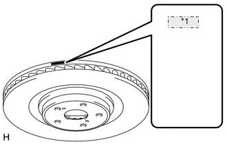
*1 RIGHT or LEFT Note
Be sure to check the identification mark when installing the disc.
Item Identification mark LH LEFT RH RIGHT
-
Align the matchmarks and install the front disc.
Note
When replacing the front disc with a new one, select the installation position where the front disc has minimal runout.
-
-
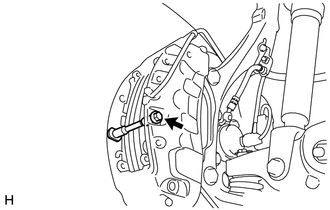
INSTALL FRONT DISC BRAKE CYLINDER ASSEMBLY
-
Install the front disc brake cylinder assembly with the new 2 bolts.
- Torque:
- 135 N*m { 1377 kgf*cm, 100 ft.*lbf }
-
-
INSTALL FRONT DISC BRAKE PAD
-
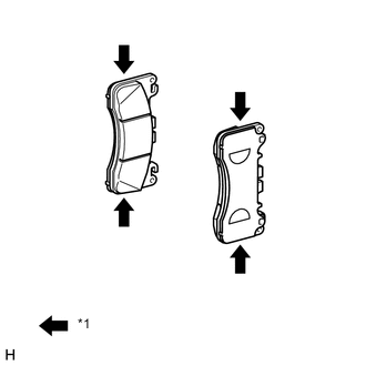
Text in Illustration *1 Disc brake grease Apply a light coat of disc brake grease to the front disc brake pads as shown in the illustration.
Note
-
When applying the disc brake grease, use the grease enclosed with a front disc brake pad kit or supplied grease (Part No. 90998-94072) or equivalent.
-
There should be no oil or grease on the friction surfaces of the pads and the disc.
-
-
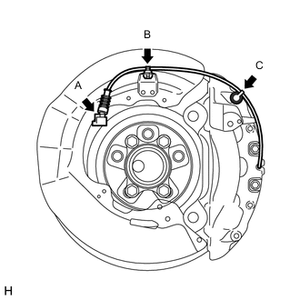
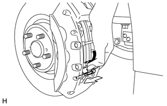
Connect the pad wear indicator wire connector (labeled A).
-
Attach the clamp (labeled B) and bleeder plug cap (labeled C).
-
Install the pad wear indicator wire and retainer to the inner pad.
-
Install the front disc brake pads to the front disc brake cylinder assembly.
-
Install the pad guide tie rod (lower) with the bolt.
- Torque:
- 30 N*m { 306 kgf*cm, 22 ft.*lbf }
-
Install the pad guide tie rod (upper) with the bolt.
- Torque:
- 30 N*m { 306 kgf*cm, 22 ft.*lbf }
-
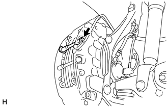
Install the anti-rattle spring to the front disc brake cylinder assembly.
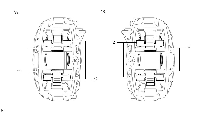
Text in Illustration *A LH Side *B RH Side *1 Pad Guide Tie Rod *2 Anti-rattle Spring Note
Securely install the anti-rattle spring in the correct position and facing the correct direction.
-
While holding the anti-rattle spring, insert the pad guide pin (lower) into the front disc brake cylinder assembly as shown in the illustration.
-
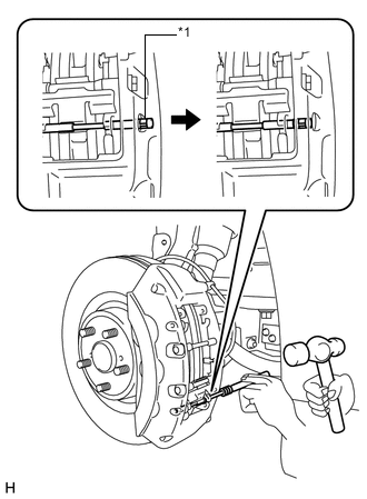
Text in Illustration *1 Ring Using a pin punch (5 mm) and hammer, install the pad guide pin (lower) to the front disc brake cylinder assembly.
Note
-
Do not damage the disc brake cylinder surface.
-
Securely attach the ring of the pad guide pin to the front disc brake cylinder assembly.
-
Make sure that the front disc brake anti-rattle spring is securely attached to the grooves of the front disc brake pad guide pin.
-
-
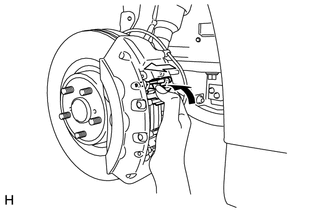
While holding the anti-rattle spring, insert the pad guide pin (upper) into the front disc brake cylinder assembly as shown in the illustration.
-
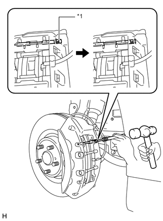
Text in Illustration *1 Ring Using a pin punch (5 mm) and hammer, install the pad guide pin (upper) to the front disc brake cylinder assembly.
Note
-
Do not damage the disc brake cylinder surface.
-
Securely attach the ring of the pad guide pin to the front disc brake cylinder assembly.
-
Make sure that the front disc brake anti-rattle spring is securely attached to the grooves of the front disc brake pad guide pin.
-
-
-
CONNECT FRONT FLEXIBLE HOSE
-
Connect the front flexible hose and a new gasket to the front disc brake cylinder assembly with a new union bolt.
- Torque:
- 39 N*m { 400 kgf*cm, 29 ft.*lbf }
Note
Install the flexible hose lock so that it fits securely in the lock hole in the disc brake cylinder assembly.
-
-
CONNECT CABLE TO NEGATIVE BATTERY TERMINAL
Note
When disconnecting the cable, some systems need to be initialized after the cable is reconnected Click here.
-
INSTALL COWL TOP VENTILATOR LOUVER RH
-
BLEED BRAKE SYSTEM
-
INSTALL FRONT WHEEL
- Torque:
- 140 N*m { 1428 kgf*cm, 103 ft.*lbf }
-
CLEAR DTC
-
CHECK FOR DTC
-
If any DTC is output, perform the troubleshooting for that DTC Click here.
-