BRAKE MASTER CYLINDER(for LHD) INSTALLATION
CAUTION / NOTICE / HINT
Note
While the battery is connected, even if the engine switch is off, the brake control system activates when the brake pedal is depressed or the door courtesy switch turns on. Therefore during servicing of the brake system components, do not operate the brake pedal and open/close the doors while the battery is connected.
PROCEDURE
-
INSTALL BRAKE BOOSTER GASKET
-
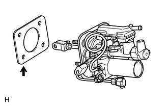
Install a new brake booster gasket to the brake master cylinder with simulator.
-
-
INSTALL BRAKE MASTER CYLINDER WITH SIMULATOR ASSEMBLY
-
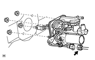
Install the brake master cylinder with simulator with the 4 nuts.
- Torque:
- 13 N*m { 130 kgf*cm, 9 ft.*lbf }
-
Connect the brake stroke simulator connector.
-
-
INSTALL PUSH ROD PIN
-
INSTALL BRAKE PEDAL RETURN SPRING
-
INSTALL RESERVOIR BRACKET
-
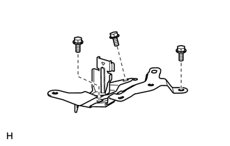
Install the reservoir bracket with the 3 bolts.
- Torque:
- 8.5 N*m { 87 kgf*cm, 75 in.*lbf }
-
-
INSTALL NO. 1 RESERVOIR HOSE
-
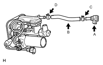
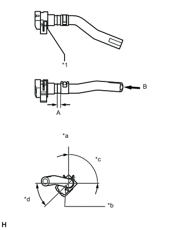
Install the reservoir connector (labeled A) to the No. 1 reservoir hose (labeled B) with the hose clip (labeled C) as shown in the illustration.
Length "A" 4.0 to 7.0 mm (0.158 to 0.276 in.) Text in Illustration *1 Reservoir Connector *a View B *b Paint Mark *c 75° to 105° *d 30° to 60° -
With the paint mark on the hose's tip facing the top of the vehicle, install the No. 1 reservoir hose (labeled B) to the master cylinder with the hose clip (labeled D).
Tech Tips
Install the hose clip so that its claws face the top of the vehicle.
-
-
INSTALL BRAKE MASTER CYLINDER RESERVOIR ASSEMBLY
-
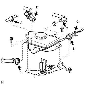
Connect the No. 1 reservoir hose (labeled F) and No. 2 brake actuator hose (labeled E) to the reservoir. The reservoir connector connecting procedure must be followed as described below:
-
Remove the foreign matter entry prevention plastic bags.
Note
Check that there is no damage or foreign objects on the connected part of the reservoir and reservoir connectors.
-
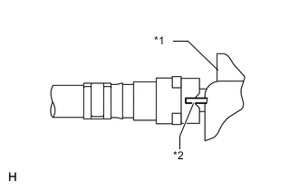
Text in Illustration *1 Reservoir *2 Rib Insert the reservoir connector to the reservoir until the reservoir connector makes a "click" sound, so that the reservoir connector tip's groove is aligned with the reservoir's rib.
-
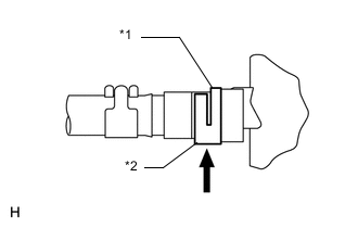
Text in Illustration *1 Claw *2 Lock Securely set the lock of the reservoir connector.
-
Check that the reservoir connector lock's claw is securely attached.
-
-
With the paint mark on the hose's tip facing the top of the vehicle, connect the No. 1 brake actuator hose (labeled D) to the reservoir with the hose clip.
Tech Tips
Install the hose clip so that its claws face the top of the vehicle.
-
Connect the brake fluid level warning switch connector (labeled C), and then attach the connector clamp (labeled B) to the reservoir bracket.
-
Install the brake fluid reservoir with the 2 bolts.
- Torque:
- 8.5 N*m { 87 kgf*cm, 75 in.*lbf }
-
Connect the wire harness clamp (labeled A) to the reservoir.
-
-
INSTALL BRAKE ACTUATOR AND BRAKE ACCUMULATOR PUMP ASSEMBLY
-
CONNECT NO. 3 RELAY BLOCK
-
INSTALL SKID CONTROL ECU BRACKET
-
INSTALL SKID CONTROL ECU
-
CONNECT CABLE TO NEGATIVE BATTERY TERMINAL
Note
-
Make sure that the 2 accumulator pump connectors are disconnected.
-
When disconnecting the cable, some systems need to be initialized after the cable is reconnected Click here.
-
-
CONNECT BRAKE ACCUMULATOR PUMP CONNECTORS
-
Add brake fluid into the reservoir between MAX and MIN line on the brake fluid reservoir.
Brake fluid SAE J1703 or FMVSS No. 116 DOT3 -
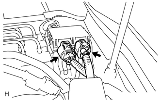
With the power switch off, connect the 2 brake accumulator pump connectors.
-
Turn the power switch on (IG) and check that the brake accumulator pump motor operates and stops.
-
Turn the power switch off.
-
-
BLEED BRAKE MASTER CYLINDER
-
CHECK AND ADJUST BRAKE PEDAL
-
INSTALL NO. 1 INSTRUMENT PANEL SAFETY PAD SUB-ASSEMBLY
-
INSTALL FRONT WHEEL
- Torque:
- 140 N*m { 1428 kgf*cm, 103 ft.*lbf }
-
INSTALL COWL TOP VENTILATOR LOUVER SUB-ASSEMBLY
-
INSTALL COWL TOP VENTILATOR LOUVER RH
-
INSTALL V-BANK COVER SUB-ASSEMBLY
-
CLEAR DTC
-
PERFORM LINEAR VALVE OFFSET LEARNING
-
When the brake master cylinder with simulator assembly is replaced, perform the linear valve offset learning Click here.
-
-
CHECK BRAKE ACTUATOR WITH TESTER
-
Check the brake actuator and pressure sensor Click here.
-
-
CHECK BRAKE MASTER CYLINDER WITH TESTER
-
Check the brake master cylinder and stroke simulator Click here.
-
-
CHECK SRS WARNING LIGHT
-
CHECK MASTER CYLINDER PRESSURE SENSOR SIGNAL
-
Check the pressure sensor signal Click here.
-
-
CHECK FOR DTC
-
If any DTC is set, perform the troubleshooting for that DTC Click here.
-
-
READ VALUE OF ACCUMULATOR PRESSURE SENSOR OUTPUT VOLTAGE