FRONT SHOCK ABSORBER(w/ Air Suspension) INSTALLATION

CAUTION / NOTICE / HINT
Tech Tips
-
Use the same procedures for the RH side and LH side.
-
The procedures listed below are for the LH side.
-
A bolt without a torque specification is shown in the standard bolt chart Click here.
PROCEDURE
-
INSTALL FRONT PNEUMATIC CYLINDER LH O-RING
Tech Tips
It is unnecessary to perform the following procedures if the pneumatic cylinder with front shock absorber has been replaced with a new one.
-
Lightly coat 2 new O-rings with MP grease.
-
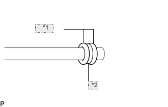
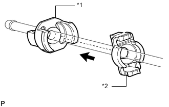
*1 O-Ring *2 Plate Install the 2 new O-rings and a new plate to a straight tube or equivalent, as shown in the illustration.
-
Insert the tube end with the 2 O-rings and plate into the pneumatic cylinder with front shock absorber LH. Then, lightly push in the O-rings and plate with a thick piece of paper.
-
While holding the O-rings and plate in place with the paper, slowly pull out the tube.
-
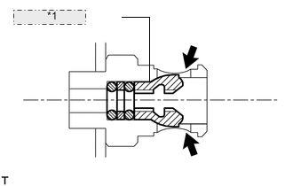
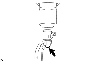
*1 Tube Connector Install a new tube connector.
Note
Push in the tube connector until a "click" sound is heard.
-
-
INSTALL PNEUMATIC CYLINDER WITH FRONT SHOCK ABSORBER ASSEMBLY LH (for 2WD)
-
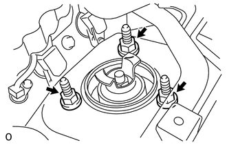
Install the pneumatic cylinder with front shock absorber assembly LH on the vehicle by installing the 3 nuts on the suspension support side.
- Torque:
- 67 N*m { 683 kgf*cm, 49 ft.*lbf }
-
-
INSTALL LOWER FRONT SHOCK ABSORBER BRACKET SUB-ASSEMBLY LH (for AWD)
-
Install the lower front shock absorber bracket sub-assembly LH to the pneumatic cylinder with front shock absorber assembly LH with the bolt.
- Torque:
- 48 N*m { 489 kgf*cm, 35 ft.*lbf }
-
-
INSTALL PNEUMATIC CYLINDER WITH FRONT SHOCK ABSORBER ASSEMBLY LH (for AWD)
*1 Attachment Note
When installing a new pneumatic cylinder with front shock absorber assembly LH:
Do not remove the attachment until the height control tube is installed.
-
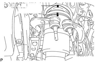
*1 Matchmark When reusing the pneumatic cylinder with front shock absorber assembly LH:
Align the matchmarks on the front suspension support assembly and pneumatic cylinder chamber.
-
Install the pneumatic cylinder with front shock absorber assembly LH on the vehicle by installing the 3 nuts on the suspension support side.
- Torque:
- 67 N*m { 683 kgf*cm, 49 ft.*lbf }
-
-
INSTALL ABSORBER CONTROL ACTUATOR
-
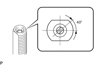
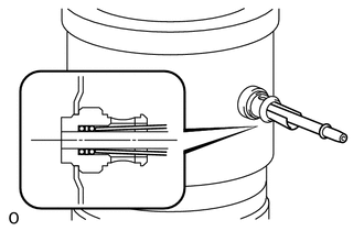
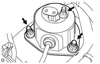
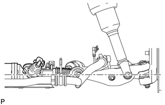
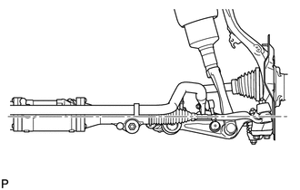
Check that the control rod of the pneumatic cylinder with front shock absorber assembly LH is in the position shown in the illustration.
Note
If the control rod is not in the position shown in the illustration, turn the control rod to adjust the position and install the absorber control actuator.
-
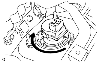
Install the absorber control actuator to the actuator support bracket. Turn the actuator clockwise approximately 40° until a click is felt.
Note
Do not excessively turn the actuator.
-
-
INSTALL FRONT SHOCK ABSORBER CAP LH (for 2WD)
-
Connect the connector to the shock absorber control actuator.
-
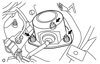
Install the shock absorber cap with the 3 nuts.
- Torque:
- 20 N*m { 204 kgf*cm, 15 ft.*lbf }
-
-
INSTALL FRONT SHOCK ABSORBER CAP LH (for AWD)
-
Connect the connector to the shock absorber control actuator.
-
Install the shock absorber cap with the 3 nuts.
- Torque:
- 20 N*m { 204 kgf*cm, 15 ft.*lbf }
-
-
INSTALL ENGINE ROOM SIDE COVER LH (for 2WD)
-
INSTALL ENGINE ROOM SIDE COVER LH (for AWD)
-
INSTALL AIR CLEANER INLET COVER SUB-ASSEMBLY (for 2WD)
-
Install the 4 clips and air cleaner inlet cover.
-
-
INSTALL AIR CLEANER INLET COVER SUB-ASSEMBLY (for AWD)
-
TEMPORARILY TIGHTEN FRONT NO. 2 SUSPENSION LOWER ARM ASSEMBLY LH (for 2WD)
-
Temporarily install the front No. 2 suspension lower arm with the nut.
Tech Tips
Tighten the nut after the vehicle is stabilized.
-
Temporarily install the front No. 2 suspension lower arm LH to the steering knuckle with the nut.
Tech Tips
Tighten the nut after the vehicle is stabilized.
-
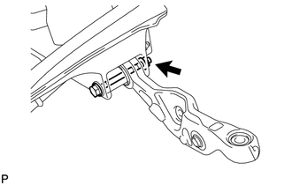
Install the bottom side of the pneumatic cylinder with front shock absorber assembly LH to the No. 2 suspension lower arm LH. Then insert the bolt from the rear of the vehicle and temporarily install it with the nut.
Tech Tips
Tighten the nut after the vehicle is stabilized.
-
-
TEMPORARILY INSTALL LOWER FRONT SHOCK ABSORBER BRACKET SUB-ASSEMBLY LH (for AWD)
-
Install the lower front shock absorber bracket sub-assembly LH to the front No. 1 suspension lower arm LH.
-
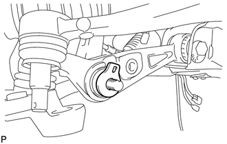
Align the protrusion of the front shock absorber upper bracket plate with cutout of the lower front shock absorber bracket sub-assembly LH, and temporarily install the nut.
-
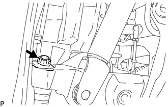
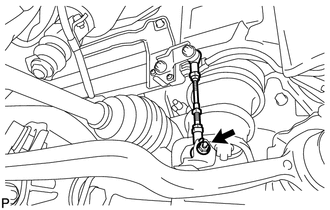
Install the skid control sensor wire to the pneumatic cylinder with front shock absorber assembly LH with the bolt.
Note
-
Do not twist the skid control sensor wire.
-
When installing the bolt, do not deform the pneumatic cylinder with front shock absorber assembly LH.
-
-
-
CONNECT NO. 4 HEIGHT CONTROL TUBE
-
*1 Attachment When installing a new pneumatic cylinder with front shock absorber assembly LH:
Remove the attachment.
-
Connect the No. 4 height control tube to the cylinder.
-
Connect the No. 1 tube connector.
-
-
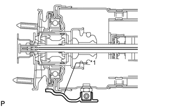
INSTALL AIR CONNECTOR CLIP HOLDER
-
*1 No. 1 Tube Connector *2 Air Connector Clip Holder Install the air connector clip holder to the No. 1 tube connector.
-
-
INSTALL FRONT STABILIZER LINK ASSEMBLY LH (for 2WD)
-
INSTALL FRONT STABILIZER LINK ASSEMBLY LH (for AWD)
-
CONNECT FRONT HEIGHT CONTROL SENSOR SUB-ASSEMBLY LH (for 2WD)
-
CONNECT FRONT HEIGHT CONTROL SENSOR SUB-ASSEMBLY LH (for AWD)
-
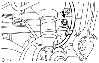
Install the bracket of the front height control sensor LH to the front No. 1 suspension lower arm LH with the bolt.
- Torque:
- 5.4 N*m { 55 kgf*cm, 48 ft.*lbf }
-
-
CONNECT FRONT NO. 1 SUSPENSION LOWER ARM ASSEMBLY LH (for 2WD)
-
INSTALL STEERING KNUCKLE SUB-ASSEMBLY LH (for AWD)
-
CONNECT FRONT NO. 1 SUSPENSION UPPER ARM ASSEMBLY LH (for AWD)
-
CONNECT FRONT NO. 2 SUSPENSION UPPER ARM ASSEMBLY LH (for AWD)
-
CONNECT TIE ROD ASSEMBLY LH
-
INSTALL FRONT SPEED SENSOR LH (for AWD)
-
CONNECT SKID CONTROL SENSOR WIRE (for AWD)
-
INSTALL FRONT DISC BRAKE DUST COVER LH
-
INSTALL FRONT DISC
-
CONNECT FRONT DISC BRAKE CALIPER ASSEMBLY LH
-
CONNECT SPEED SENSOR CONNECTOR (for 2WD)
-
INSTALL FRONT AXLE SHAFT NUT LH (for AWD)
-
CONNECT CABLE TO NEGATIVE BATTERY TERMINAL
-
INSTALL COWL TOP VENTILATOR LOUVER
-
PERFORM INITIALIZATION
-
Perform the initialization Click here.
Note
Certain systems need to be initialized after disconnecting and reconnecting the cable from the negative (-) battery terminal.
-
-
STABILIZE SUSPENSION (for 2WD)
-
Install the front wheel.
- Torque:
- 140 N*m { 1428 kgf*cm, 103 ft.*lbf }
-
Lower the vehicle and start the engine. Then fill the pneumatic cylinder with front shock absorber assembly LH with air.
-
Bounce the vehicle up and down several times to stabilize the front suspension.
-
Remove the front wheel.
Note
Do not turn the engine switch on (IG).
-
Jack up the front suspension lower arm with a wooden block between the jack and front suspension lower arm. Apply a load to the front suspension so that the front suspension lower arm is placed in a horizontal position.
-
-
STABILIZE SUSPENSION (for AWD)
-
Install the front wheels.
- Torque:
- 140 N*m { 1428 kgf*cm, 103 ft.*lbf }
-
Lower the vehicle and start the engine. Then fill the pneumatic cylinder with front shock absorber assembly LH with air.
Tech Tips
If the vehicle height is not restored within 2 minutes, stop the engine and then start the engine again.
-
Bounce the vehicle up and down several times to stabilize the front suspension.
-
Remove the front wheels.
Note
Do not turn the power switch ON (IG).
-
Jack up the front suspension lower arm with a wooden block between the jack and front suspension lower arm. Apply a load to the front suspension so that the front suspension lower arm is horizontal.
-
-
TIGHTEN FRONT NO. 2 SUSPENSION LOWER ARM ASSEMBLY LH (for 2WD)
-
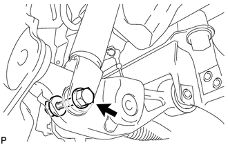
TIGHTEN LOWER FRONT SHOCK ABSORBER BRACKET SUB-ASSEMBLY LH (for AWD)
-
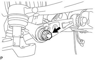
Tighten the lower side nut of the lower front shock absorber bracket sub-assembly LH.
- Torque:
- 112 N*m { 1142 kgf*cm, 83 ft.*lbf }
-
-
INSTALL FRONT WHEEL
- Torque:
- 140 N*m { 1428 kgf*cm, 103 ft.*lbf }
-
INSPECT AND ADJUST FRONT WHEEL ALIGNMENT (for 2WD)
-
Check and adjust the front wheel alignment Click here.
-
-
INSPECT AND ADJUST FRONT WHEEL ALIGNMENT (for AWD)
-
Check and adjust the front wheel alignment Click here.
-
-
INSPECT FOR AIR LEAK
-
Inspect for air leak Click here.
-
-
ADJUST VEHICLE HEIGHT
-
Adjust the vehicle height Click here.
-
-
ADJUST HEADLIGHT ASSEMBLY
-
Adjust the headlight assembly Click here.
-
-
ADJUST OBJECT RECOGNITION CAMERA
-
Adjust the object recognition camera Click here.
-