METER / GAUGE SYSTEM Tachometer Malfunction
DESCRIPTION
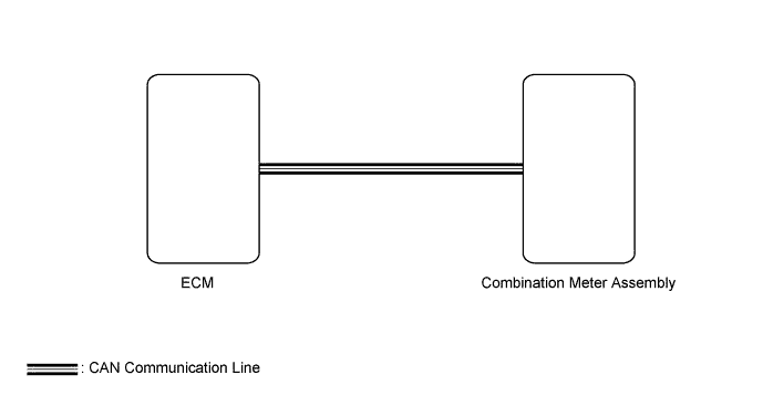
The combination meter assembly receivers engine speed signals from the ECM via the CAN communication line. The combination meter assembly displays engine speed data that is calculated based on the data received from the ECM.
WIRING DIAGRAM
INSPECTION PROCEDURE
Note
-
Before starting following inspection, check if the SFI system*1 or ECD*2 system troubleshooting.
-
*1: for 1TR-FE, 2TR-FE
-
*2: for 1KD-FTV, 2KD-FTV, 5L-E
-
for 1TR-FE: Click here
-
for 2TR-FE (w/ Secondary Air Injection System): Click here
-
for 2TR-FE (w/o Secondary Air Injection System): Click here
-
for 1KD-FTV (w/ DPF): Click here
-
for 1KD-FTV (w/o DPF): Click here
-
for 2KD-FTV: Click here
-
for 5L-E: Click here
-
The meter/gauge system uses the CAN communication system. First inspect the communication systems by following How to Proceed with Troubleshooting Click here. Troubleshoot the meter/gauge system after confirming that the communication systems are functioning properly.
PROCEDURE
-
CHECK FOR DTC (SFI SYSTEM*1 OR ECD SYSTEM*2)
-
*1: for 1TR-FE, 2TR-FE
-
*2: for 1KD-FTV, 2KD-FTV, 5L-E
-
Clear the DTCs Click here.
-
Check for DTCs Click here.
OK SFI system *1 or ECD*2 system DTCs are not output. Result Result Proceed to OK A NG (for 1TR-FE) B NG (for 2TR-FE) NG (for 1KD-FTV) C NG (for 2KD-FTV) NG (for 5L-E) Tech Tips
*: Go to procedure;
-
for 1TR-FE: Click here
-
for 2TR-FE (w/ Secondary Air Injection System): Click here
-
for 2TR-FE (w/o Secondary Air Injection System): Click here
-
for 1KD-FTV (w/ DPF): Click here
-
for 1KD-FTV (w/o DPF): Click here
-
for 2KD-FTV: Click here
-
for 5L-E: Click here
-
B 
GO TO SFI SYSTEM*
C
GO TO ECD SYSTEM*
A 
-
-
PERFORM ACTIVE TEST USING GTS (TACHOMETER)
-
Use the Active Test to check the operation of the tachometer Click here.
Combination Meter Tester Display Test Part Control Range Diagnostic Note Tacho Meter Operation Tachometer OFF, 0, 1000, 2000, 3000, 4000, 5000, 6000 or 7000 (rpm) - Tech Tips
Make sure that the vehicle is stopped and the engine is idling.
OK Needle indication is normal.
NG
REPLACE COMBINATION METER ASSEMBLY Click here
OK
-
-
READ VALUE USING GTS (ENGINE SPEED)
-
Use the Data List to check if the tachometer is operating properly Click here.
Combination Meter Tester Display Measurement Item/Range Normal Condition Diagnostic Note Engine Rpm Engine speed / Min.: 0 rpm, Max.: 12750 rpm Actual engine speed - OK Engine speed displayed on the GTS is almost the same as the actual engine speed.
NG
REPLACE COMBINATION METER ASSEMBLY Click here
OK
-
-
READ VALUE USING GTS
-
Use the Data List to check if the tachometer is operating properly Click here.
Combination Meter Tester Display Measurement Item/Range Normal Condition Diagnostic Note Engine Rpm Engine speed / Min.: 0 rpm, Max.: 12750 rpm Actual engine speed - Engine and ECT Tester Display Measurement Item/Range Normal Condition Diagnostic Note Engine Speed Engine speed / Min.: 0 rpm, Max.: 16383 rpm 650 to 750 rpm: When idling - OK The data list values of the ECUs match. Tech Tips
-
When the Data List values of the ECUs match, an internal malfunction of the combination meter assembly is suspected.
-
When the Data List values of the ECUs do not match, a signal output error of the ECM or an internal malfunction of the combination meter assembly is suspected.
*: Replacement procedure;
-
for 1TR-FE: Click here
-
for 2TR-FE: Click here
-
for 1KD-FTV: Click here
-
for 2KD-FTV: Click here
-
for 5L-E: Click here
-
NG
REPLACE ECM*
OK
-
-
CHECK COMBINATION METER ASSEMBLY
-
Temporarily replace the combination meter assembly with a new one or normally functioning one Click here.
-
Check that the operation of the tachometer returns to normal Click here.
Tech Tips
*: Replacement procedure;
-
for 1TR-FE: Click here
-
for 2TR-FE: Click here
-
for 1KD-FTV: Click here
-
for 2KD-FTV: Click here
-
for 5L-E: Click here
-
NG
REPLACE ECM*
OK 
END (COMBINATION METER ASSEMBLY IS DEFECTIVE)
-