ECD SYSTEM (w/o DPF), Diagnostic DTC:P2009, P2010
| DTC Code | DTC Name |
|---|---|
| P2009 | Intake Manifold Runner Control Circuit Low (Bank 1) |
| P2010 | Intake Manifold Runner Control Circuit High (Bank 1) |
DESCRIPTION
Refer to DTC P2006 Click here.
| DTC Detection Drive Pattern | DTC Detection Condition | Trouble Area |
|---|---|---|
| 2 seconds after engine is started, race engine for 1 second | Open in vacuum switching valve (for swirl control valve) circuit for 0.5 seconds (2 trip detection logic). |
|
| DTC Detection Drive Pattern | DTC Detection Condition | Trouble Area |
|---|---|---|
| 2 seconds after engine is started, race engine for 1 second | Short in vacuum switching valve (for swirl control valve) circuit for 0.5 seconds (2 trip detection logic). |
|
WIRING DIAGRAM
Refer to DTC P2006 Click here.
INSPECTION PROCEDURE
Note
-
After replacing the ECM, the new ECM needs registration Click here and initialization Click here.
-
Inspect the fuses for circuits related to this system before performing the following inspection procedure.
Tech Tips
Read freeze frame data using the GTS. Freeze frame data records the engine condition when a malfunction is detected. When troubleshooting, freeze frame data can help determine if the vehicle was moving or stationary, if the engine was warmed up or not, and other data from the time the malfunction occurred.
PROCEDURE
-
PERFORM ACTIVE TEST USING GTS (ACTIVATE THE VSV FOR SWIRL CONTROL VALVE)
-
Connect the GTS to the DLC3.
-
Disconnect the vacuum hoses from the vacuum switching valve (for Swirl Control Valve).
-
Turn the ignition switch to ON and turn the GTS on.
-
Enter the following menus: Powertrain / Engine and ECT / Active Test / Activate the VSV for Swirl Control Valve.
-
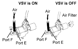
Check the VSV operation when it is operated using the GTS.
OK GTS Operation Specified Condition VSV ON Air from port E flows out through port F VSV OFF Air from port E flows out through air filter -
Reconnect the vacuum hoses.
NG 
INSPECT VACUUM SWITCHING VALVE FOR SWIRL CONTROL VALVE (RESISTANCE) Click here
OK 
CHECK FOR INTERMITTENT PROBLEMS Click here
-
-
INSPECT VACUUM SWITCHING VALVE FOR SWIRL CONTROL VALVE (RESISTANCE)
-
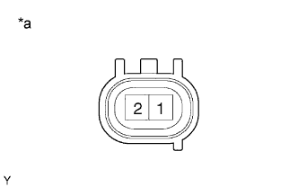
Text in Illustration *a Component without harness connected
(VSV for Swirl Control Valve)
Disconnect the VSV for swirl control valve connector.
-
Measure the resistance according to the value(s) in the table below.
Standard Resistance Tester Connection Specified Condition 1 - 2 33 to 39 Ω at 20°C (68°F) -
Reconnect the VSV for swirl control valve connector.
NG
REPLACE VACUUM SWITCHING VALVE (FOR SWIRL CONTROL VALVE) Click here
OK 
-
-
CHECK VACUUM SWITCHING VALVE (FOR SWIRL CONTROL VALVE) (POWER SOURCE VOLTAGE)
-
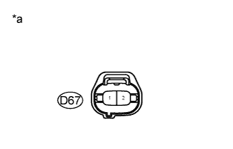
Text in Illustration *a Front view of wire harness connector
(to Vacuum Switching Valve [for Swirl Control Valve])
Disconnect the vacuum switching valve (for swirl control valve) connector.
-
Measure the voltage according to the value(s) in the table below.
Standard Voltage Tester Connection Switch Condition Specified Condition D67-2 - Body ground Ignition switch ON 11 to 14 V
NG
CHECK HARNESS AND CONNECTOR (VACUUM SWITCHING VALVE [FOR SWIRL CONTROL VALVE] - NO. 1 INTEGRATION RELAY) Click here
OK
-
-
CHECK HARNESS AND CONNECTOR (VACUUM SWITCHING VALVE (FOR SWIRL CONTROL VALVE) - ECM)
-
Disconnect the vacuum switching valve (for swirl control valve) connector.
-
Disconnect the ECM connector.
-
Measure the resistance according to the value(s) in the table below.
Standard Resistance Tester Connection Condition Specified Condition D67-1 - D98-108 (SCV) Always Below 1 Ω D67-1 or D98-108 (SCV) - Body ground Always 10 kΩ or higher -
Reconnect the vacuum switching valve (for swirl control valve) connector.
-
Reconnect the ECM connector.
NG
REPAIR OR REPLACE HARNESS OR CONNECTOR Click here
OK
-
-
REPLACE ECM
-
Replace the ECM Click here.
NEXT
CONFIRM WHETHER MALFUNCTION HAS BEEN SUCCESSFULLY REPAIRED Click here
-
-
CHECK HARNESS AND CONNECTOR (VACUUM SWITCHING VALVE [FOR SWIRL CONTROL VALVE] - NO. 1 INTEGRATION RELAY)
-
Remove the No. 1 integration relay from the No. 1 engine room relay block and junction block assembly.
-
Disconnect the No. 1 integration relay connector.
-
Disconnect the vacuum switching valve (for swirl control valve) connector.
-
Measure the resistance according to the value(s) in the table below.
Standard Resistance (Check for Open) Tester Connection Condition Specified Condition 10B-4 - D67-2 Always Below 1 Ω 10B-4 or D67-2 - Body ground Always 10 kΩ or higher -
Reinstall the No. 1 integration relay.
-
Reconnect the No. 1 integration relay connector.
-
Reconnect the vacuum switching valve (for swirl control valve) connector.
NG
REPAIR OR REPLACE HARNESS OR CONNECTOR Click here
OK
-
-
INSPECT ECM POWER SOURCE CIRCUIT
-
Check the ECM power source circuit Click here.
NEXT
CONFIRM WHETHER MALFUNCTION HAS BEEN SUCCESSFULLY REPAIRED Click here
-
-
REPLACE VACUUM SWITCHING VALVE (FOR SWIRL CONTROL VALVE)
-
Replace the vacuum switching valve (for swirl control valve).
NEXT
CONFIRM WHETHER MALFUNCTION HAS BEEN SUCCESSFULLY REPAIRED Click here
-
-
REPAIR OR REPLACE HARNESS OR CONNECTOR
-
Repair or replace harness or connector.
NEXT
-
-
CONFIRM WHETHER MALFUNCTION HAS BEEN SUCCESSFULLY REPAIRED
-
Connect the GTS to the DLC3.
-
Clear the DTCs Click here.
-
Start the engine and wait for 3 seconds or more.
-
Enter the following menus: Powertrain / Engine and ECT / Trouble Codes.
-
Confirm that the DTC is not output again.
NEXT
END
-