ENGINE (for 2WD) INSTALLATION

CAUTION:
As the engine assembly with transmission is extremely heavy, the engine lifter may suddenly drop if the instructions listed in the repair manual are not followed. Therefore, always follow the instructions listed in the repair manual when performing this procedure.
-
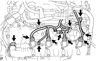
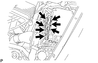
INSTALL IGNITION COIL ASSEMBLY
-
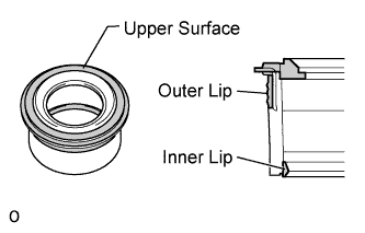
Perform a visual inspection of the spark plug tube gasket.
Standard Area Specified condition Upper surface No scratches or deformation Outer lip No scratches or deformation Inner lip No scratches If the result is not as specified, replace the spark plug tube gasket.
-
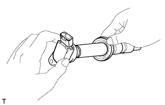
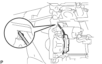
Slide the spark plug tube gasket onto the ignition coil assembly as shown in the illustration.
-
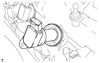
After installing the spark plug tube gasket, firmly insert the ignition coil assembly as shown in the illustration.
-
Install the 8 bolts.
- Torque:
- 10 N*m { 102 kgf*cm, 7 ft.*lbf }
-
Connect the 8 ignition coil assembly connectors.
-
-
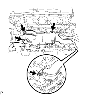
INSTALL KNOCK SENSOR
-
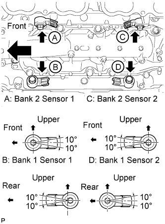
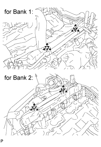
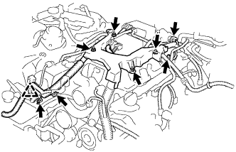
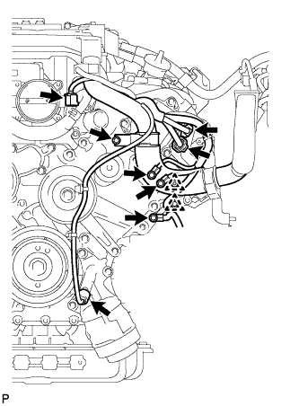
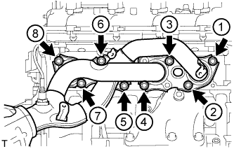
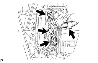
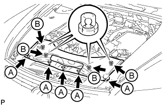
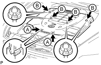
Install the 4 knock sensors with the 4 bolts so that the sensors are angled as shown in the illustration.
- Torque:
- 20 N*m { 204 kgf*cm, 15 ft.*lbf }
Tech Tips
The acceptable installation angle of the sensors is between 10° upwards and downwards from the horizontal position.
-
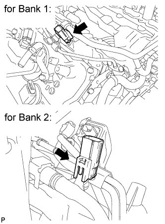
Connect the 4 knock sensor connectors.
-
-
INSTALL ENGINE COOLANT TEMPERATURE SENSOR
-
Install a new gasket to the engine coolant temperature sensor.
-
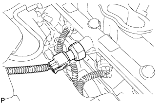
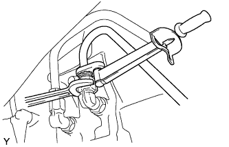
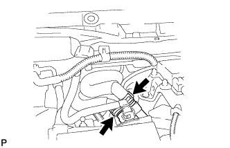
Using a 19 mm ball joint lock nut wrench, install the engine coolant temperature sensor.
- Torque:
- 20 N*m { 200 kgf*cm, 14 ft.*lbf }
Note
-
Do not use a tool such as an impact wrench or equivalent.
-
Use the torque value compensation formula to calculate the torque value for use when a torque wrench is combined with a tool such as a ball joint lock nut wrench Click here.
-
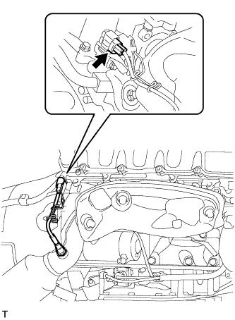
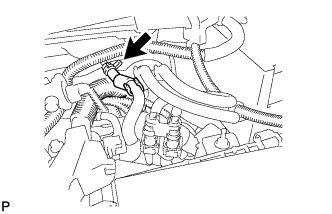
Connect the engine coolant temperature sensor connector.
-
-
INSTALL ENGINE OIL LEVEL SENSOR
-
Install a new gasket to the engine oil level sensor.
-
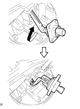
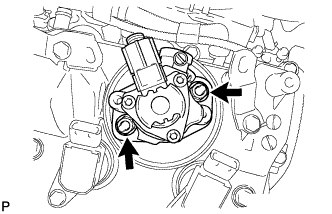
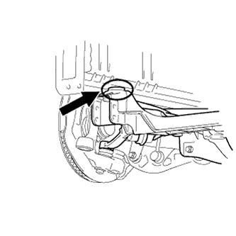
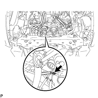
Insert the engine oil level sensor into the oil pan and rotate it 180°.
-
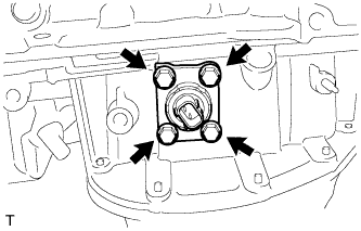
Install the engine oil level sensor with the 4 bolts.
- Torque:
- 7.0 N*m { 71 kgf*cm, 62 in.*lbf }
-
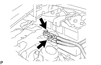
Connect the engine oil level sensor connector.
-
-
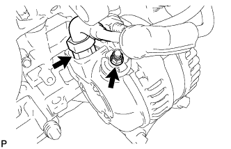
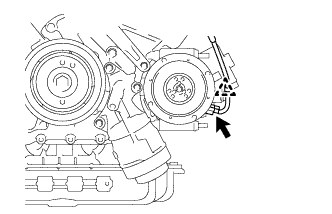
INSTALL ENGINE OIL PRESSURE SWITCH ASSEMBLY
-
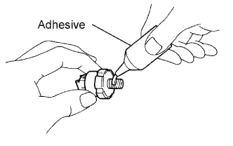
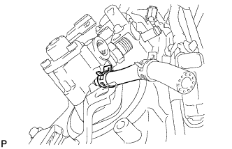
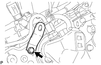
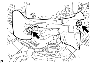
Apply adhesive to 2 or 3 threads of the switch.
Adhesive Toyota Genuine Adhesive 1344, Three Bond 1344 or equivalent -
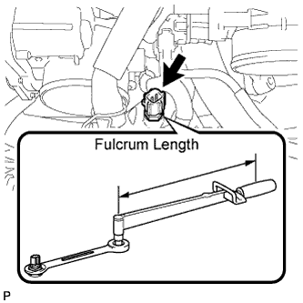
Using a 24 mm deep socket wrench, install the switch.
- Torque:
- 15 N*m { 153 kgf*cm, 11 ft.*lbf }
Note
Do not start the engine within 1 hour after installation.
-
Connect the switch connector.
-
-
INSTALL WATER INLET HOUSING
-
Install a new gasket to the water pump.
-
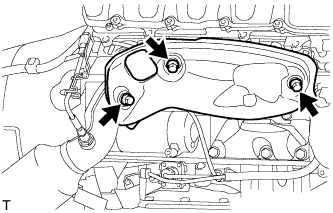
Install the water inlet housing with the 3 bolts.
- Torque:
- 21 N*m { 214 kgf*cm, 15 ft.*lbf }
-
-
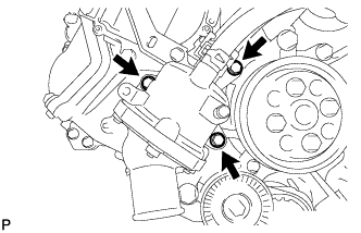
INSTALL WATER PUMP PULLEY
-
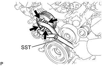
Temporarily install the pulley with the 4 bolts.
-
Using SST, hold the pulley and tighten the 4 bolts.
- SST
- 09960-10010 ( 09962-01000, 09963-01000 )
- Torque:
- 21 N*m { 214 kgf*cm, 15 ft.*lbf }
-
-
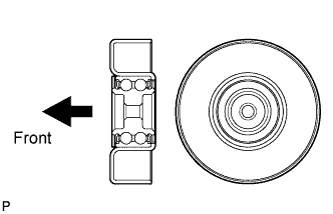
INSTALL NO. 1 IDLER PULLEY SUB-ASSEMBLY
-
Install the No. 1 idler pulley sub-assembly with the bolt.
- Torque:
- 43 N*m { 438 kgf*cm, 32 ft.*lbf }
Tech Tips
Install the No. 1 idler pulley sub-assembly in the direction shown in the illustration.
-
-
INSTALL NO. 2 IDLER PULLEY SUB-ASSEMBLY
-
Install the No. 2 idler pulley sub-assembly with the bolt.
- Torque:
- 43 N*m { 438 kgf*cm, 32 ft.*lbf }
-
-
INSTALL NO. 4 ENGINE COVER SUB-ASSEMBLY
-
Install the No. 4 engine cover sub-assembly.
-
-
INSTALL ENGINE WIRE
-
Install the engine wire with the 2 bolts.
- Torque:
- 10 N*m { 102 kgf*cm, 7 ft.*lbf }
-
Connect the 4 knock sensor connectors.
-
-
INSTALL SEPARATOR CASE
-
Install the separator case with the 4 bolts.
- Torque:
- 10 N*m { 102 kgf*cm, 7 ft.*lbf }
-
Connect the fuel pressure sensor connector.
-
-
INSTALL FUEL INJECTOR ASSEMBLY (for Direct Injection)
-
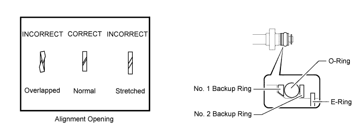
Install a new O-ring, new No. 1 backup ring, new No. 2 backup ring, new No. 3 backup ring and a new E-ring to the fuel injector assembly as shown in the illustration.
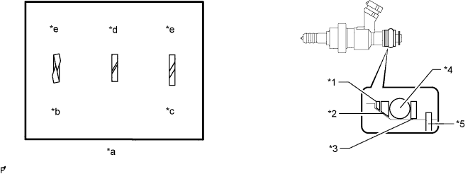
Text in Illustration *1 No. 1 Backup Ring *2 No. 2 Backup Ring *3 No. 3 Backup Ring *4 O-Ring *5 E-Ring - - *a Alignment Opening *b Overlapped *c Stretched *d CORRECT *e INCORRECT - - Note
-
Check that there is no foreign matter or damaged areas in the fuel injector assembly O-ring groove.
-
Check that the No. 1 backup ring and No. 2 backup ring are installed in the correct direction.
-
Make sure that the No. 1 backup ring, No. 2 backup ring, No. 3 backup ring and O-ring are installed in the correct order.
-
Check that the alignment openings of the No. 1 backup ring, No. 2 backup ring and No. 3 backup ring are not overlapped or stretched as shown in the illustration.
-
After installing the O-ring, check that it is not contaminated with foreign matter and is not damaged.
-
-
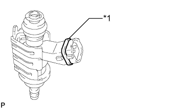
Install the injector nozzle holder clamp.
-
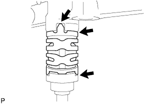
Text in Illustration *1 Insulator Color Apply engine oil to the O-ring. Install the nozzle holder clamp by aligning the protruding part of the clamp to the notch of the fuel delivery pipe.
Note
-
Make sure there is no gasoline on the O-ring and inside the installation hole.
-
The fuel injector assembly connectors can be differentiated by the color of the insulators, which are black, yellow, green or brown. Install the fuel injector assemblies so that insulators are the same color for a given bank.
-
Make sure that there is no gap between the fuel delivery pipe and injector nozzle holder clamp.
-
Check that there is no foreign matter or damage to the fuel injector assembly insertion hole of the fuel delivery pipe.
-
Insert the fuel injector assembly straight into the fuel delivery pipe without tilting it.
-
-
-
-
INSTALL NO. 2 FUEL DELIVERY PIPE (for Direct Injection)
-
Install 4 new injector vibration insulators to the cylinder head.
-
Apply lubricant to the fuel injector seal and installation holes.
-
Install the No. 2 fuel delivery pipe (with fuel injector assemblies) to the cylinder head with the 5 bolts.
- Torque:
- 21 N*m { 214 kgf*cm, 15 ft.*lbf }
Note
-
If a fuel injector assembly is dropped or the tip of the fuel injector assembly is struck, replace it with a new one.
-
Check that there is no foreign matter or damage to the fuel injector assembly insertion hole of the cylinder head.
-
When inserting the No. 2 fuel delivery pipe, push it in evenly without tilting it.
-
Connect the 4 fuel injector connectors.
-
Connect the fuel pressure sensor connector.
-
-
INSTALL FUEL DELIVERY PIPE (for Direct Injection)
-
Install 4 new injector vibration insulators to the cylinder head.
-
Apply lubricant to the fuel injector seal and installation holes.
-
Install the fuel delivery pipe (with fuel injector assemblies) to the cylinder head with the 5 bolts.
- Torque:
- 21 N*m { 214 kgf*cm, 15 ft.*lbf }
Note
-
If a fuel injector assembly is dropped or the tip of the fuel injector assembly is struck, replace it with a new one.
-
Check that there is no foreign matter or damage to the fuel injector assembly insertion hole of the cylinder head.
-
When inserting the fuel delivery pipe, push it in evenly without tilting it.
-
Connect the 4 fuel injector connectors.
-
Connect the No. 3 fuel hose.
-
-
INSTALL NO. 4 FUEL PIPE SUB-ASSEMBLY
-
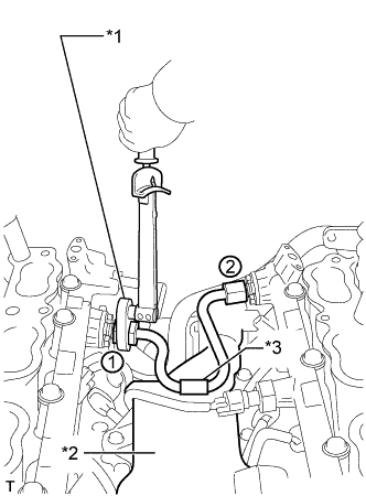
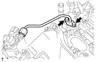
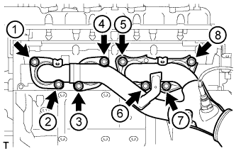
Text in Illustration *1 Union Nut Wrench *2 Separator Case *3 Fuel Pipe Protector Temporarily install the No. 4 fuel pipe sub-assembly.
-
Using a 19 mm union nut wrench, tighten the No. 4 fuel pipe sub-assembly in the order shown in the illustration.
- Torque:
- 30 N*m { 306 kgf*cm, 22 ft.*lbf }
Note
-
After installing the No. 4 fuel pipe sub-assembly, check that the fuel pipe protector contacts with the separator case.
-
Use the formula to calculate special torque values for situations where a union nut wrench is combined with a torque wrench Click here.
-
-
INSTALL FUEL PUMP ASSEMBLY (for High Pressure)
-
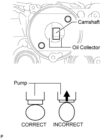
Turn the camshaft until the flat of the cam is facing the cylinder head cover's fuel pump attachment hole, as shown in the illustration.
Tech Tips
By not using the camshaft lobe to push up the pump lifter surface, it is easier to install the fuel pump and No. 3 fuel pipe later.
-
Pour 30 cm3(1.8 cu. in.) of engine oil through the cylinder head cover's fuel pump attachment hole into the cylinder head oil collector.
-
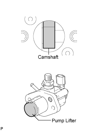
Apply a coat of engine oil to the pump activation cam and pump lifter.
-
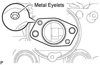
Install a new fuel pump insulator to the cylinder head cover. Then pass the 2 stud bolts through the holes of the fuel pump and set them on the insulator.
Note
Install the insulator so that the open sides of the metal eyelets are facing outward, as shown in the illustration.
-
Temporarily install the fuel pump with the 2 nuts.
-
Connect the fuel hose.
-
-
INSTALL NO. 3 FUEL PIPE SUB-ASSEMBLY
-
Install a new O-ring, new backup rings (No. 1 and No. 2) and new E-ring to the fuel injector as shown in the illustration.
Note
-
Check that there is no foreign matter or damaged areas in the injector's O-ring groove.
-
Check that the No. 1 and No. 2 backup rings are installed in the correct direction.
-
Make sure that the backup rings and O-ring are installed in the correct order.
-
Check that the alignment openings of the backup rings are not overlapped or stretched as shown in the illustration.
-
After installing the O-ring, check that it is not contaminated with foreign matter and is not damaged.
-
-
Apply engine oil to the O-ring.
Note
Make sure there is no gasoline on the O-ring and inside the installation hole.
-
Temporarily install the No. 3 fuel pipe to the delivery pipe with the 2 bolts.
-
Temporarily install the No. 3 fuel pipe sub-assembly to the fuel pump.
Note
Be careful not to damage the sealing surface of the fuel pipe when temporarily installing the fuel pipe.
-
Tighten the 2 bolts in several passes.
- Torque:
- 10 N*m { 102 kgf*cm, 7 ft.*lbf }
-
Tighten the 2 nuts in several passes.
- Torque:
- 25 N*m { 255 kgf*cm, 18 ft.*lbf }
-
Using a 19 mm union nut wrench, tighten the union nut.
- Torque:
- 30 N*m { 306 kgf*cm, 22 ft.*lbf }
Note
-
There must be absolutely no free play in the union on the fuel pump side. If the union on the fuel pump side has free play, replace the fuel pump.
-
Use the formula to calculate special torque values for situations where a union nut wrench is combined with a torque wrench Click here.
-
Connect the fuel pump connector.
-
-
INSTALL NO. 2 FUEL PIPE SUB-ASSEMBLY
Tech Tips
The installation procedures are the same as the No. 3 fuel pipe sub-assembly.
-
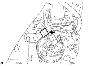
INSTALL FUEL PRESSURE PULSATION DAMPER ASSEMBLY
-
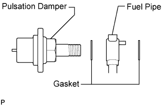
Apply a light coat of engine oil to the threads and gasket seating surfaces of the 2 fuel pressure pulsation damper assemblies.
-
Temporarily install each dampers together with 2 new gaskets and the pipe to the fuel pump.
-
Install the 2 clamp bolts.
- Torque:
- 10 N*m { 102 kgf*cm, 7 ft.*lbf }
-
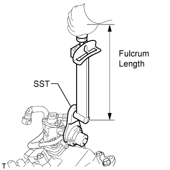
Using SST, tighten the 2 dampers.
- SST
- 09612-24014 ( 09617-24011 )
- Torque:
- without SST
- 36 N*m { 367 kgf*cm, 27 ft.*lbf }
- with SST
- 31 N*m { 313 kgf*cm, 23 ft.*lbf }
Note
There must be absolutely no free play in the union on the fuel pump side. If the union on the fuel pump side has free play, replace the fuel pump.
Tech Tips
-
Use a torque wrench with a fulcrum length of 300 mm (11.8 in.). When using a torque wrench with a fulcrum length that is not 300 mm (11.8 in.). calculate the torque specification for the torque wrench and SST based on the "without SST" torque specification Click here.
-
Make sure SST and the torque wrench are connected in a straight line.
-
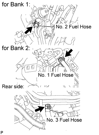
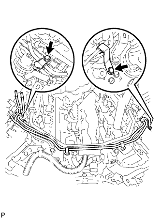
Connect the 3 fuel hoses.
-
Connect the connector to the delivery pipe.
-
Install the bracket with the bolt.
- Torque:
- 10 N*m { 102 kgf*cm, 7 ft.*lbf }
-
-
INSTALL ENGINE COVER SUB-ASSEMBLY
-
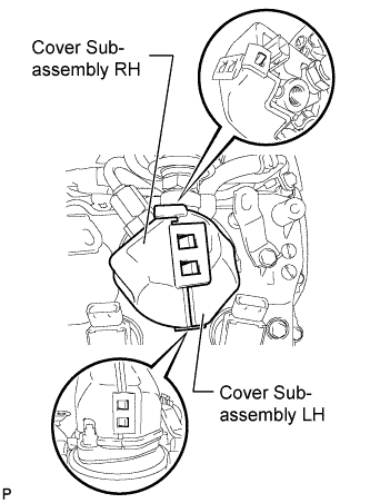
Attach the 5 claws and install the engine cover LH and RH to the fuel pump.
-
-
INSTALL FUEL INJECTOR ASSEMBLY (for Port Injection)
-
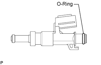
Apply gasoline to a new O-ring and install it to the injector.
Note
Check that there is no damage or foreign material in the groove of the injector when installing the injector O-ring.
-
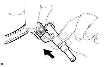
Connect the connector to the injector.
-
Install the injector to the delivery pipe as shown in the illustration.
Note
-
Make sure that there are no scratches or foreign matter in or around the insertion hole of the delivery pipe.
-
When inserting the injector, be careful not to damage the O-ring.
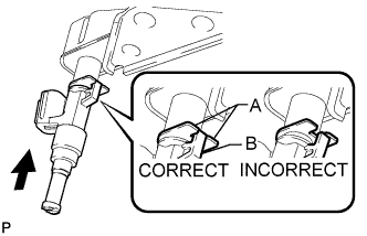
-
Attach the part of the injector labeled B between the parts of the delivery pipe labeled A.
-
-
-
INSTALL FUEL DELIVERY PIPE (for Port Injection)
-
Install the 4 delivery pipe spacers and 8 insulators to the cylinder head.
-
Install the 2 delivery pipes (with injector) to the cylinder head.
-
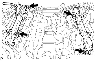
Install the 4 bolts.
- Torque:
- 21 N*m { 214 kgf*cm, 15 ft.*lbf }
Note
Check that the part of the injector labeled B is between the parts of the delivery pipe labeled A.
-
Connect the 4 wire harness clamps.
-
Connect the 2 delivery pipe connectors.
-
-
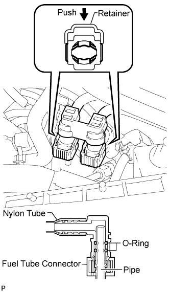
INSTALL FUEL TUBE SUB-ASSEMBLY
-
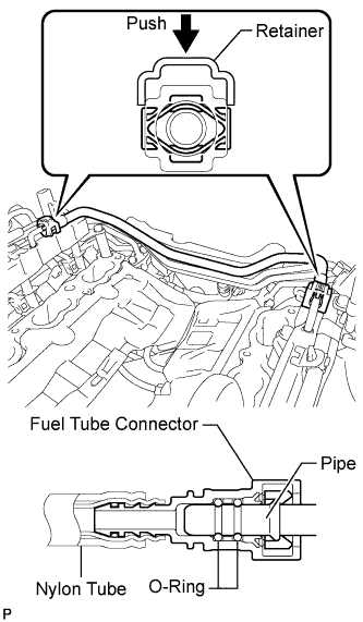
Push in the tube connector to the pipe until the tube connector makes a "click" sound.
-
Push down on the retainer to lock it in place.
Note
-
Check that there is no damage or foreign objects on the connected part of the fuel pipe.
-
After connecting, check that the fuel tube connector and the pipe are securely connected by pulling on them.
-
-
-
INSTALL NO. 3 COVER SUB-ASSEMBLY
-
Install the No. 3 engine cover with the 2 clips.
-
Install the bracket with the 2 bolts.
- Torque:
- 10 N*m { 102 kgf*cm, 7 ft.*lbf }
-
-
INSTALL NO. 2 ENGINE COVER SUB-ASSEMBLY LH
-
INSTALL NO. 2 ENGINE COVER SUB-ASSEMBLY
-
INSTALL NO. 1 ENGINE COVER SUB-ASSEMBLY
-
INSTALL INTAKE MANIFOLD
-
Install 2 new gasket to the intake manifold.
-
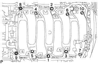
Temporarily install the intake manifold with the 2 nuts and 8 bolts. Then tighten the 2 nuts and 8 bolts uniformly in the order shown in the illustration.
- Torque:
- 21 N*m { 214 kgf*cm, 15 ft.*lbf }
-
Connect the No. 1 ventilation hose to the intake manifold.
Note
Make sure that the clip is facing as shown in the illustration.
-
-
INSTALL THROTTLE BODY ASSEMBLY
-
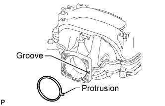
Install a new gasket to the intake manifold.
Tech Tips
Align the protrusion of the gasket with the groove on the intake manifold.
-
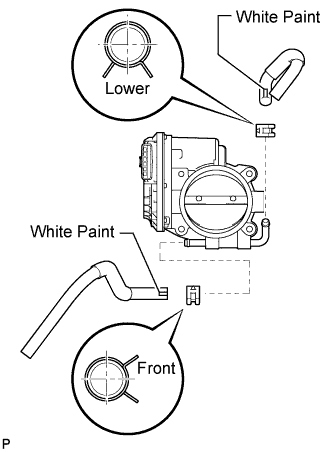
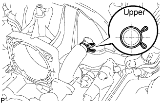
Connect the No. 4 and No. 5 water by-pass hoses to the throttle body assembly.
Note
-
Position the claws of the clamps as shown in the illustration.
-
Install the clamps so that they are within the hose's paint marks.
-
-
Install the throttle body assembly with the 4 bolts.
- Torque:
- 10 N*m { 102 kgf*cm, 7 ft.*lbf }
-
Connect the throttle motor connector.
-
-
INSTALL VENTILATION HOSE
-
INSTALL WATER BY-PASS PIPE SUB-ASSEMBLY
-
Install the water by-pass pipe sub-assembly to the intake manifold with the 2 bolts.
- Torque:
- 10 N*m { 102 kgf*cm, 7 ft.*lbf }
-
Connect the heater water inlet hose, heater water outlet hose, water inlet hose, and No. 3 water by-pass hose to the water by-pass pipe sub-assembly with the 4 clamps.
Note
Make sure that the No. 3 water by-pass hose clip is facing as shown in the illustration.
-
-
INSTALL NO. 2 ENGINE COVER (for LHD)
-
Install the No. 2 engine cover with the 4 nuts.
- Torque:
- 21 N*m { 214 kgf*cm, 15 ft.*lbf }
-
-
INSTALL NO. 1 ENGINE COVER
-
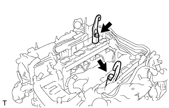
INSTALL INJECTOR DRIVER
-
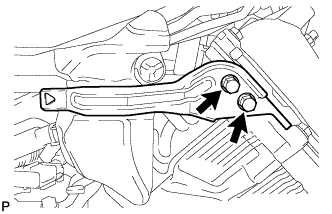
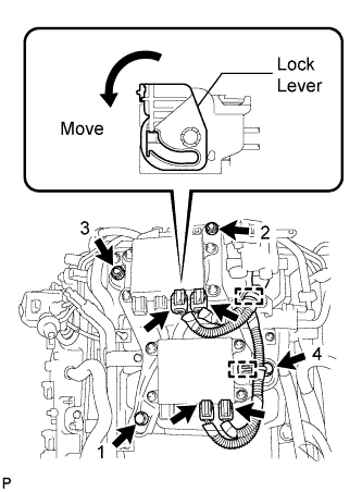
Install the injector driver to the intake manifold by installing the 2 bolts and 2 nuts in the order shown in the illustration.
- Torque:
- 10 N*m { 102 kgf*cm, 7 ft.*lbf }
-
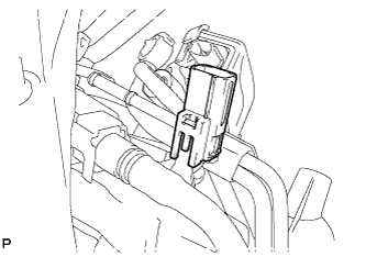
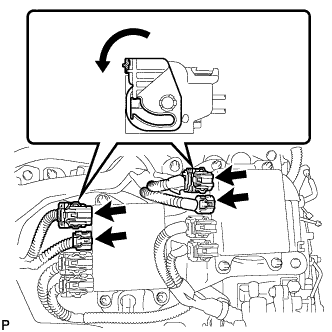
Connect the 4 wire harness connectors to the injector driver. Then move the lock lever as shown in the illustration to lock the connectors.
-
Connect the 2 clamps to the injector driver.
-
-
INSTALL FRONT NO. 1 ENGINE MOUNTING BRACKET RH
-
Install the front No. 1 engine mounting bracket RH with the 6 bolts.
- Torque:
- 35 N*m { 357 kgf*cm, 26 ft.*lbf }
-
-
INSTALL FRONT NO. 1 ENGINE MOUNTING BRACKET LH
-
Install the front No. 1 engine mounting bracket LH with the 6 bolts.
- Torque:
- 35 N*m { 357 kgf*cm, 26 ft.*lbf }
-
-
INSTALL ENGINE MOUNTING DAMPER
-
Install the 2 engine mounting dampers with the 2 nuts.
- Torque:
- 11 N*m { 112 kgf*cm, 8 ft.*lbf }
-
-
INSTALL GENERATOR ASSEMBLY
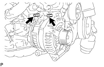
-
Using an E8 "TORX" socket wrench, set the generator with the 2 stud bolts.
- Torque:
- 10 N*m { 102 kgf*cm, 7 ft.*lbf }
-
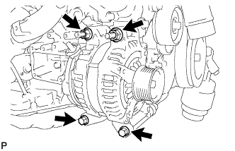
Install the generator with the 2 bolts and 2 nuts.
- Torque:
- 43 N*m { 438 kgf*cm, 32 ft.*lbf }
-
Connect the generator connector.
-
Connect the harness to the +B terminal with the nut.
- Torque:
- 12 N*m { 122 kgf*cm, 9 ft.*lbf }
-
-
INSTALL FRONT ENGINE MOUNTING INSULATOR
Tech Tips
Perform this procedure only when replacement of the front engine mounting insulator is necessary.
-
Install the 2 front engine mounting insulators with the 2 nuts.
- Torque:
- 64 N*m { 653 kgf*cm, 47 ft.*lbf }
-
-
INSTALL ENGINE MOUNTING SPACER
-
Install the 2 engine mounting spacers.
-
-
INSTALL NO. 1 ENGINE HANGER
-
Install the 2 No. 1 engine hangers with the 2 bolts as shown in the illustration.
- Torque:
- 43 N*m { 438 kgf*cm, 32 ft.*lbf }
Tech Tips
No. 1 engine hanger 12281-38150 Bolt 90119-14120 -
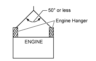
Attach an engine sling device and hang the engine with a chain block.
Note
When hanging the engine, make sure to hang the engine with the sling device's hanging angle at 50° or less. If not, the engine or No. 1 engine hangers may be damaged.
-
-
REMOVE ENGINE STAND
-
Lift the engine and remove it from the engine stand.
Note
With the exception of installing the engine assembly to an engine stand or removing the engine assembly from an engine stand, do not perform any work on the engine while it is suspended, as doing so is dangerous.
-
Place the engine onto a work bench.
-
-
INSTALL FRONT SUSPENSION CROSSMEMBER SUB-ASSEMBLY
-
Install the front suspension crossmember sub-assembly with the 2 nuts.
- Torque:
- 35 N*m { 357 kgf*cm, 26 ft.*lbf }
-
-
INSTALL DRIVE PLATE AND RING GEAR SUB-ASSEMBLY
-
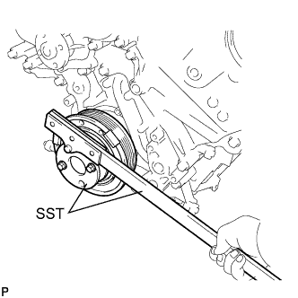
Using SST, hold the crankshaft.
- SST
- 09213-54015 ( 90119-08216 )
- 09330-00021
-
Clean the their installation holes.
-
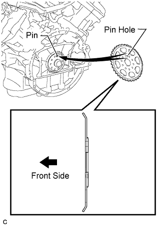
Install the crankshaft position sensor rotor.
Tech Tips
-
Align the pin of the crankshaft with the pin hole of the crankshaft position sensor rotor.
-
As the crankshaft position sensor rotor are not reversible, be sure to install it in the direction shown in the illustration.
-
-
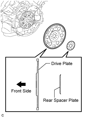
Install the drive plate and ring gear sub-assembly and rear spacer plate on the crankshaft.
Tech Tips
As the drive plate and ring gear sub-assembly and rear spacer plate are not reversible, be sure to install it in the direction shown in the illustration.
-
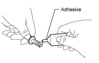
Apply a few drops of adhesive to 2 or 3 threads of the bolt end.
Adhesive Toyota Genuine Adhesive 1324, Three Bond 1324 or equivalent -
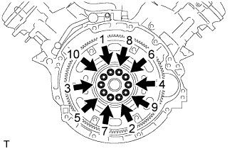
Uniformly install and tighten 10 new bolts in the sequence shown in the illustration.
- Torque:
- 30 N*m { 301 kgf*cm, 22 ft.*lbf }
Note
-
Do not reuse the drive plate installation bolts.
-
Do not impact or damage the drive plate installation bolts. Be sure to handle them carefully.
-
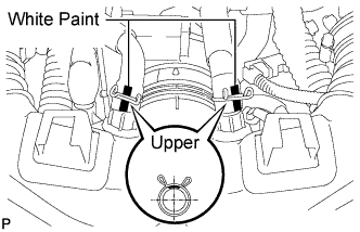
Mark the upside of each drive plate installation bolt with paint.
-
Retighten the drive plate installation bolts by 90°.
-
Check that the painted marks are now at a 90° angle to the upside.
-
-
INSTALL AUTOMATIC TRANSMISSION ASSEMBLY
-
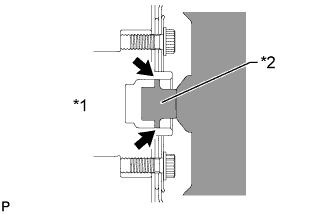
Text in Illustration *1 Crankshaft *2 Torque Converter Centerpiece Apply clutch spline grease to the circumference of the crankshaft contact surface with the torque converter centerpiece.
Clutch spline grease Toyota Genuine Clutch Spline Grease or equivalent Maximum spread About 1 g (0.0353 oz.) -
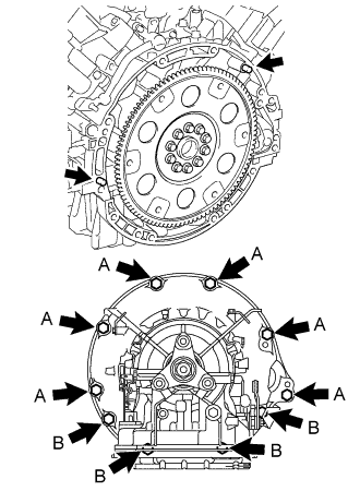
Confirm that 2 knock pins are on the transmission contact surface of the engine block before transmission installation.
- Torque:
- for Bolt A (17 mm head bolt)
- 71 N*m { 724 kgf*cm, 52 ft.*lbf }
- for Bolt B (14 mm head bolt)
- 37 N*m { 377 kgf*cm, 27 ft.*lbf }
Note
-
Make sure that the mark is positioned as shown in the illustration.
-
Do not use excess force to pry on the automatic transmission assembly.
-
-
INSTALL DRIVE PLATE AND TORQUE CONVERTER SETTING BOLT
-
Turn the crankshaft to gain access to the installation locations of the 6 torque converter setting bolts and install each bolt while holding the crankshaft pulley bolt with a wrench.
- Torque:
- 48 N*m { 489 kgf*cm, 35 ft.*lbf }
Note
First install the black colored bolt, and then the remaining 5 silver colored bolts.
-
-
INSTALL STARTER ASSEMBLY
-
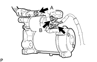
Connect the starter connector.
-
Connect the starter wire with the 2 nuts.
- Torque:
- for nut A
- 10 N*m { 102 kgf*cm, 7 ft.*lbf }
- for nut B
- 9.8 N*m { 100 kgf*cm, 87 in.*lbf }
-
Close the terminal cap.
-
Install the starter assembly with the 2 bolts.
- Torque:
- 37 N*m { 377 kgf*cm, 27 ft.*lbf }
Note
Make sure the flywheel housing side cover is as shown in the illustration.
-
-
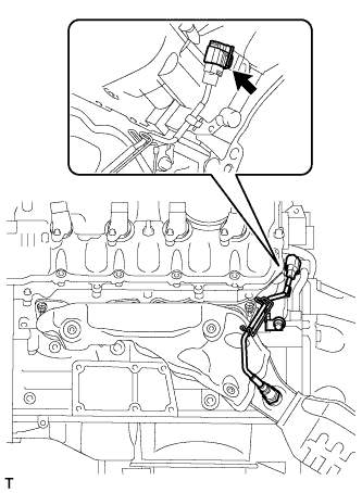
INSTALL ENGINE WIRE
-
Install the engine wire with the 4 nuts.
- Torque:
- 10 N*m { 102 kgf*cm, 7 ft.*lbf }
-
Connect the clamp and 2 clamp brackets with the 2 bolts.
- Torque:
- 10 N*m { 102 kgf*cm, 7 ft.*lbf }
-
Connect the intake air control valve actuator connector.
-
Connect the purge VSV connector.
-
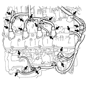
Connect the 4 injector driver connectors as shown in the illustration.
-
for Engine RH Side:
-
Connect the 2 clamps and install the 3 clamp brackets with the 3 bolts.
- Torque:
- 10 N*m { 102 kgf*cm, 7 ft.*lbf }
-
Connect the engine oil level sensor connector.
-
Connect the crankshaft position sensor connector.
-
Connect the starter connector and starter wire with the nut.
- Torque:
- 10 N*m { 102 kgf*cm, 7 ft.*lbf }
-
Connect the generator connector and generator wire with the nut.
- Torque:
- 12 N*m { 122 kgf*cm, 9 ft.*lbf }
-
Connect the camshaft position sensor connector.
-
Connect the engine wire connector.
-
Connect the 2 camshaft timing control motor connectors. (for Bank 2)
-
Connect the fuel pump connector. (for high pressure)
-
Connect the 2 VVT sensor connectors.
-
Connect the 4 ignition coil connectors.
-
Connect the camshaft timing control valve connector.
-
-
for Engine LH Side:
-
Install the clamp bracket with the bolt.
- Torque:
- 10 N*m { 102 kgf*cm, 7 ft.*lbf }
-
Connect the 3 clamps and 3 ground wires with the 3 bolts.
- Torque:
- 10 N*m { 102 kgf*cm, 7 ft.*lbf }
-
Connect the 2 camshaft timing control motor connectors. (for Bank 1)
-
Connect the oil pressure switch connector.
-
Connect the engine coolant temperature sensor connector.
-
Connect the clamp and install the 2 clamp brackets with the 2 bolts.
- Torque:
- 10 N*m { 102 kgf*cm, 7 ft.*lbf }
-
Connect the No. 8 engine wire connector.
-
Connect the fuel pump connector. (for high pressure)
-
Connect the 2 VVT sensor connectors.
-
Connect the 4 ignition coil connectors.
-
Connect the camshaft timing control valve connector.
-
-
Connect the throttle body connectors.
-
-
INSTALL NO. 3 EXHAUST MANIFOLD HEAT INSULATOR
-
Install the No. 3 exhaust manifold heat insulator with the 3 bolts.
- Torque:
- 10 N*m { 102 kgf*cm, 7 ft.*lbf }
-
-
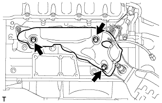
INSTALL OIL COOLER TUBE
-
Temporarily install the oil cooler tube inlet and oil cooler tube outlet.
-
Install the 2 clamps with the 2 bolts.
- Torque:
- 5.5 N*m { 56 kgf*cm, 49 in.*lbf }
-
Using a union nut wrench, tighten the union nuts of the oil cooler tube inlet and oil cooler tube outlet.
- Torque:
- 44 N*m { 450 kgf*cm, 33 ft.*lbf }
Note
Use the formula to calculate special torque values for situations where a union nut wrench is combined with a torque wrench Click here.
-
-
INSTALL EXHAUST MANIFOLD SUB-ASSEMBLY (for Bank 2)
-
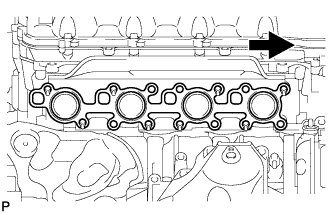
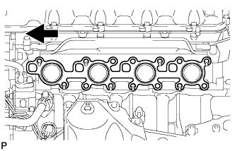
Install a new gasket.
Text in Illustration 
Front -
Install the exhaust manifold RH, and install 8 new nuts in the order shown in the illustration.
- Torque:
- 21 N*m { 214 kgf*cm, 15 ft.*lbf }
-
-
INSTALL NO. 1 EXHAUST MANIFOLD HEAT INSULATOR
-
Install the No. 1 exhaust manifold heat insulator with the 3 bolts.
- Torque:
- 10 N*m { 102 kgf*cm, 7 ft.*lbf }
-
Connect the air fuel ratio sensor connector.
-
-
INSTALL ENGINE OIL LEVEL DIPSTICK GUIDE
-
Apply a light coat of engine oil to a new O-ring.
-
Install the O-ring to the engine oil level dipstick guide.
-
Install the engine oil level dipstick guide with the 2 bolts.
- Torque:
- 10 N*m { 102 kgf*cm, 7 ft.*lbf }
-
Install the engine oil level dipstick.
-
-
INSTALL ENGINE AND TRANSMISSION
-
Place the engine on an engine lifter.
Note
-
Place wooden blocks or plate lift attachments so that the engine is level.
-
With the exception of installing the engine assembly to an engine stand or removing the engine assembly from an engine stand, do not perform any work on the engine while it is suspended, as doing so is dangerous.
-
Never install attachments to the oil pan of the engine assembly or transmission as doing so may deform the oil pan.
-
-
Remove the 2 bolts and 2 No. 1 engine hangers.
-
Operate the engine lifter and install the engine to the vehicle.
Note
Make sure that the engine is clear of all wiring and hoses.
-
Align the crossmember to the marks on the vehicle, and temporarily install the engine and transmission with crossmember with the 4 bolts.
Note
Make sure the crossmember is aligned to the vehicle marks as accurately as possible. If not performed accurately, the suspension alignment may become extremely misaligned.
-
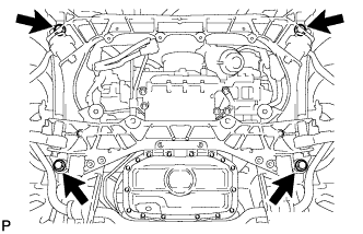
Tighten the 4 bolts.
- Torque:
- 165 N*m { 1683 kgf*cm, 122 ft.*lbf }
-
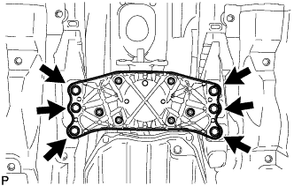
Install the 6 engine rear mounting member's bolts.
- Torque:
- 35 N*m { 354 kgf*cm, 26 ft.*lbf }
-
-
CONNECT FLOOR SHIFT GEAR SHIFTING ROD SUB-ASSEMBLY
-
Temporarily connect the floor shift gear sifting rod sub-assembly to the connecting rod swivel with the nut.
Tech Tips
The nut will be tightened to a torque specification during the shift lever position adjustment procedure.
-
-
CONNECT FRONT NO. 2 LOWER SUSPENSION ARM ASSEMBLY
-
CONNECT COOLER COMPRESSOR ASSEMBLY
-
Connect the cooler compressor assembly with the 2 stud bolts, 2 nuts and 2 bolts.
- Torque:
- for stud bolts
- 10 N*m { 102 kgf*cm, 7 ft.*lbf }
- for nuts
- 25 N*m { 255 kgf*cm, 18 ft.*lbf }
- for bolts
- 25 N*m { 255 kgf*cm, 18 ft.*lbf }
-
-
INSTALL EXHAUST MANIFOLD SUB-ASSEMBLY (for Bank 1)
-
Install a new gasket.
Text in Illustration Front -
Install the exhaust manifold LH, and install 8 new nuts in the order shown in the illustration.
- Torque:
- 21 N*m { 214 kgf*cm, 15 ft.*lbf }
-
-
INSTALL NO. 2 EXHAUST MANIFOLD HEAT INSULATOR
-
Install the exhaust manifold heat insulator with the 3 bolts.
- Torque:
- 10 N*m { 102 kgf*cm, 7 ft.*lbf }
-
Connect the air fuel ratio sensor connector.
-
-
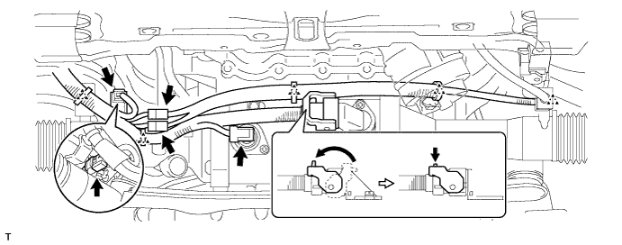
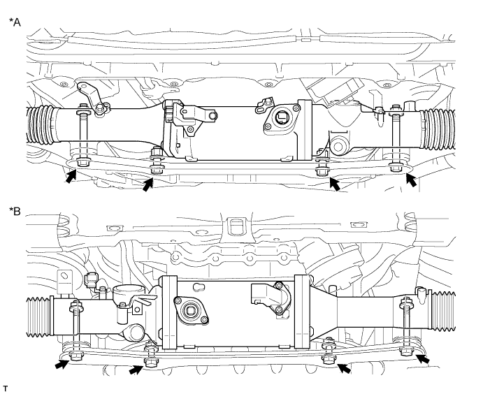
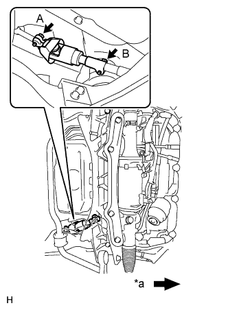
INSTALL POWER STEERING LINK ASSEMBLY (w/ VGRS)
-
Install the power steering link and rack housing bracket to the front frame with the 4 bolts and 4 nuts.
- Torque:
- 70 N*m { 714 kgf*cm, 52 ft.*lbf }
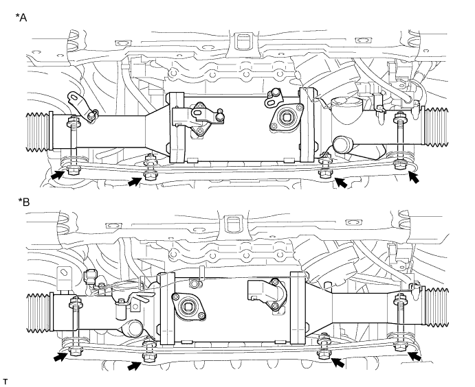
Text in Illustration *A for LHD *B for RHD -
for LHD:
Connect the 5 connectors and attach the 3 clips.
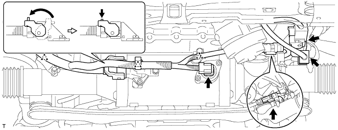
-
for RHD:
Connect the 5 connectors and attach the 5 clips.
-
-
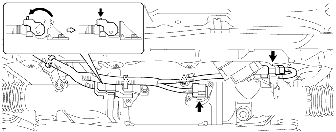
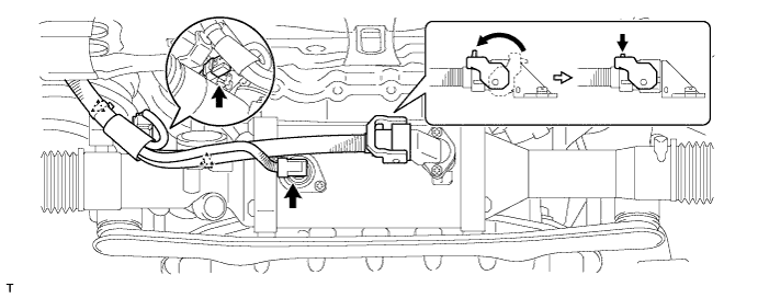
INSTALL POWER STEERING LINK ASSEMBLY (w/o VGRS)
-
Install the power steering link and rack housing bracket to the front frame with the 4 bolts and 4 nuts.
- Torque:
- 70 N*m { 714 kgf*cm, 52 ft.*lbf }
Text in Illustration *A for LHD *B for RHD -
for LHD:
Connect the 3 connectors and attach the 3 clips.
-
for RHD:
Connect the 3 connectors and attach the 2 clips.
-
-
INSTALL NO. 2 STEERING INTERMEDIATE SHAFT ASSEMBLY
-
Install the clamp to the steering column hole shield.
-
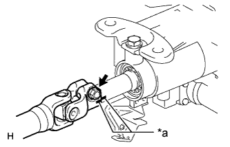
Text in Illustration *a Matchmark Align the matchmarks on the No. 2 steering intermediate shaft and steering column.
-
Install the bolt.
- Torque:
- 35 N*m { 360 kgf*cm, 26 ft.*lbf }
-
-
INSTALL STEERING SLIDING YOKE WITH SHAFT SUB-ASSEMBLY (w/ VGRS)
-
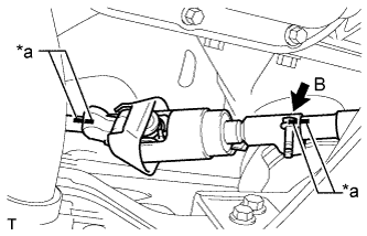
Text in Illustration *a Matchmark Align the matchmarks on the No. 2 steering intermediate shaft assembly and steering sliding with shaft yoke.
-
Align the matchmarks on the steering sliding with shaft yoke and power steering link.
-
Temporarily install bolt B.
Note
Do not tighten the bolt.
-
Text in Illustration *a Front of the vehicle Install bolt A and tighten bolt B.
- Torque:
- 35 N*m { 360 kgf*cm, 26 ft.*lbf }
-
-
INSTALL STEERING SLIDING YOKE WITH SHAFT SUB-ASSEMBLY (w/o VGRS)
-
Text in Illustration *a Matchmark Align the matchmarks on the No. 2 steering intermediate shaft and steering sliding with shaft yoke.
-
Align the matchmarks on the steering sliding with shaft yoke and steering intermediate shaft.
-
Temporarily install bolt B.
Note
Do not tighten the bolt.
-
Text in Illustration *a Front of the vehicle Install bolt A and tighten bolt B.
- Torque:
- 35 N*m { 360 kgf*cm, 26 ft.*lbf }
-
-
INSTALL FRONT SUSPENSION MEMBER REINFORCEMENT LH
-
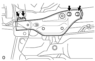
Install the front suspension member reinforcement LH to the vehicle with the 4 bolts.
- Torque:
- 50 N*m { 510 kgf*cm, 37 ft.*lbf }
-
-
INSTALL FRONT SUSPENSION MEMBER REINFORCEMENT RH
Tech Tips
Install the RH side following the same procedures as the LH side.
-
INSTALL FRONT STABILIZER BAR
-
INSTALL PROPELLER WITH CENTER BEARING SHAFT ASSEMBLY
-
INSTALL NO. 1 EXHAUST PIPE SUPPORT BRACKET SUB-ASSEMBLY
-
Install the No. 1 exhaust pipe support bracket sub-assembly with the 2 bolts.
- Torque:
- 43 N*m { 438 kgf*cm, 32 ft.*lbf }
-
-
INSTALL FRONT EXHAUST PIPE ASSEMBLY
-
CONNECT HOSES AND CONNECTORS
-
Connect the purge line hose.
-
Connect the 2 heater hoses.
-
Connect the wires with No. 1 engine room junction block with the 2 nuts.
- Torque:
- 13 N*m { 133 kgf*cm, 10 ft.*lbf }
-
Connect the ground wire with the bolt.
- Torque:
- 21 N*m { 214 kgf*cm, 15 ft.*lbf }
-
Connect the 3 connectors with front controller with the clamp.
-
Attach the clamp and connect the cooler compressor connector.
-
Connect the 3 TCM connectors and 4 ECM connectors.
-
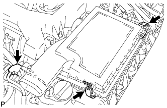
Install the engine room ECU cover.
-
-
CONNECT NO. 1 FUEL PIPE SUB-ASSEMBLY
-
Push in the tube connector to the pipe until the tube connector makes a "click" sound.
-
Push down on the retainer to lock it in place.
Note
-
Check that there is no damage or foreign objects on the connected part of the fuel pipe.
-
After connecting, check that the fuel tube connector and the pipe are securely connected by pulling on them.
-
-
-
CONNECT NO. 3 FUEL HOSE
-
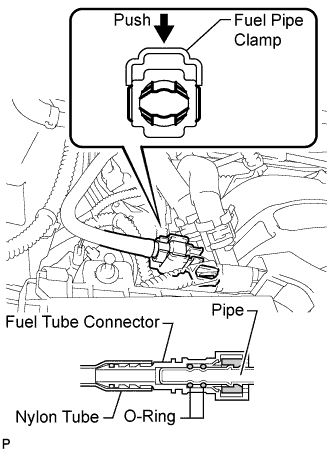
Push in the tube connector to the pipe until the tube connector makes a "click" sound.
-
Install the fuel pipe clamp.
Note
-
Check that there is no damage or foreign objects on the connected part of the fuel pipe.
-
After connecting, check that the fuel tube connector and the pipe are securely connected by pulling on them.
-
-
-
INSTALL ENGINE ROOM ECU OUTLET DUCT
-
Install the engine room ECU outlet duct.
-
-
CONNECT NO. 2 RADIATOR HOSE
-
CONNECT NO. 1 RADIATOR HOSE
-
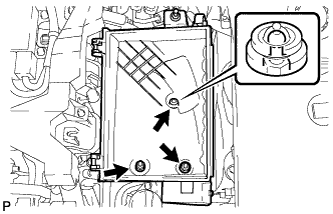
INSTALL AIR CLEANER ASSEMBLY RH
-
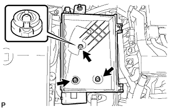
Install the air cleaner case RH with the 2 nuts and clip.
- Torque:
- 5.0 N*m { 51 kgf*cm, 44 in.*lbf }
-
Install the air cleaner filter element to the air cleaner case RH.
-
Install the air cleaner cap RH with the 2 clamps.
-
Connect the mass air flow meter connector.
-
-
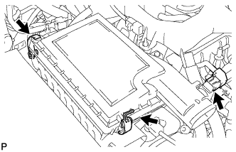
INSTALL AIR CLEANER ASSEMBLY LH
-
Install the air cleaner case LH with the 2 nuts and clip.
- Torque:
- 5.0 N*m { 51 kgf*cm, 44 in.*lbf }
-
Install the air cleaner filter element to the air cleaner case LH.
-
Install the air cleaner cap LH with the 2 clamps.
-
Connect the mass air flow meter connector.
-
-
INSTALL V-RIBBED BELT
-
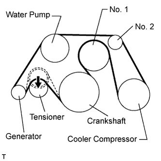
Install the V-ribbed belt as shown in the illustration.
Note
Check that the V-ribbed belt is properly set to each pulley.
-
Rotate the tensioner pulley counterclockwise, and then remove the fix bar.
-
-
-
INSTALL INTAKE AIR CONNECTOR PIPE
-
Install the intake air sound creator.
Tech Tips
Only perform this procedure when replacement of the intake air sound creator is necessary.
-
Install the intake air sound creator with the bolt and hose clamp.
- Torque:
- 2.0 N*m { 20 kgf*cm, 18 in.*lbf }
-
-
Align the protrusion of the intake air resonator with the cutout of the bracket and insert the protrusion.
-
Install the intake air connector pipe with the 3 hose clamps.
- Torque:
- for intake air connector pipe and throttle body
- 4.8 N*m { 49 kgf*cm, 42 in.*lbf }
- for intake air connector pipe and air cleaner cap
- 3.8 N*m { 39 kgf*cm, 34 in.*lbf }
Tech Tips
-
Insert the protrusion of the intake air connector pipe into the hole of the hose clamp.
-
The intake air connector pipe and throttle body clamp can be tightened within the range of 4.0 N*m (41 kgf*cm, 35 in.*lbf) to 5.5 N*m (56 kgf*cm, 49 in.*lbf), and the intake air connector pipe and air cleaner cap clamp can be tightened within the range of 2.0 N*m (20 kgf*cm, 18 in.*lbf) to 5.5 N*m (56 kgf*cm, 49 in.*lbf).
-
Attach the 2 wire harness clamps.
-
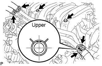
Connect the No. 1 and No. 2 ventilation hoses to the intake air connector pipe.
Tech Tips
-
Position the claws of the clamps as shown in the illustration.
-
Install the clamps so that they are within the hose's paint marks.
-
-
-
INSTALL NO. 1 AIR CLEANER INLET
-
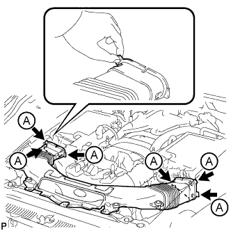
Align the holes with the connection areas labeled A, and attach the No. 1 air cleaner inlet.
-
Install the No. 1 air cleaner inlet with the 2 bolts.
- Torque:
- 5.0 N*m { 51 kgf*cm, 44 in.*lbf }
-
-
INSTALL REAR FRAME SIDE RAIL
-
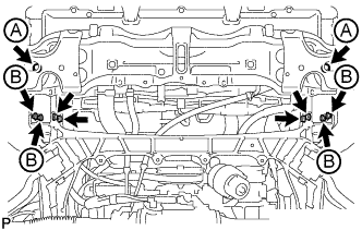
Install the 2 rear frame side rails with the 6 bolts and 4 nuts.
- Torque:
- for bolt A
- 30 N*m { 306 kgf*cm, 22 ft.*lbf }
- for nut B
- 44 N*m { 453 kgf*cm, 33 ft.*lbf }
-
-
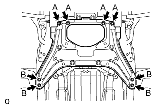
INSTALL FRONT SUSPENSION LOWER CROSSMEMBER
-
Install the front suspension lower crossmember with the 4 bolts.
- Torque:
- 25 N*m { 255 kgf*cm, 18 ft.*lbf }
-
Install the 2 clips.
-
-
INSTALL FRONT BUMPER COVER
-
CONNECT NO. 1 OIL COOLER OUTLET HOSE
-
Connect the No. 1 oil cooler outlet hose to the radiator.
-
-
CONNECT NO. 1 OIL COOLER INLET HOSE
-
Connect the No. 1 oil cooler inlet hose to the radiator.
-
-
ADD ENGINE OIL
-
Add fresh engine oil.
Standard engine oil Oil grade Oil Viscosity (SAE) API grade SL "energy-conserving", SM "energy-conserving", SN "resource-conserving" or ILSAC multigrade engine oil 0W-20
5W-20
5W-30
10W-30
API grade SL, SM or SN multigrade engine oil 15W-40
20W-50
Standard capacity Item Specified Condition Drain and refill without oil filter change 8.4 liters (8.9 US qts, 7.4 Imp. qts) Drain and refill with oil filter change 8.6 liters (9.1 US qts, 7.6 Imp. qts) Dry fill 10.2 liters (10.8 US qts, 9.0 Imp. qts) -
Install the oil filler cap.
-
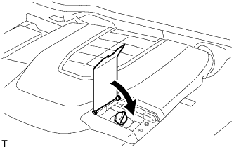
Close the oil filler cap service hole cover.
-
-
ADD ENGINE COOLANT
Standard Capacity Item Radiator Core Thickness [mm] Specified Condition for 2WD 16 11.0 liters (11.6 US qts, 9.7 Imp. qts) 27 11.8 liters (12.5 US qts, 10.4 Imp. qts) for AWD 16 11.1 liters (11.7 US qts, 9.8 Imp. qts) CAUTION:
Do not remove the radiator reservoir cap while the engine and radiator are still hot. Pressurized hot engine coolant and steam may be released and cause serious burns.
Tech Tips
Before adding coolant, turn the A/C switch off.
-
Tighten the radiator drain cock plug.
-
Tighten the 2 cylinder block drain cock plugs.
- Torque:
- 13 N*m { 133 kgf*cm, 10 ft.*lbf }
-
Add TOYOTA Super Long Life Coolant (SLLC) into the radiator reservoir.
Capacity 5.0 liters (5.3 US qts, 4.4 Imp. qts) Tech Tips
-
TOYOTA vehicles are filled with TOYOTA SLLC at the factory. In order to avoid damage to the engine cooling system and other technical problems, only use TOYOTA SLLC or similar high quality ethylene glycol based non-silicate, non-amine, non-nitrite, non-borate coolant with long-life hybrid organic acid technology (coolant with long-life hybrid organic acid technology consists of a combination of low phosphates and organic acids).
-
Please contact any authorized TOYOTA dealer or repairer or another duly qualified and equipped professional for further details.
-
The thermostat open timing can be confirmed by pressing the inlet radiator hose by hand, and checking when the coolant starts to flow inside the hose.
-
-
Further add coolant into the radiator reservoir until it reaches the FULL line.
-
Press the No. 1 and No. 2 radiator hoses several times by hand, and then check the coolant level.
If the coolant level is low, add coolant.
-
Using a 6 mm hexagon wrench, install the vent plug.
- Torque:
- 1.5 N*m { 15 kgf*cm, 13 in.*lbf }
-
Bleed air from the cooling system.
Note
Before starting the engine to warm up the engine, turn the A/C switch off.
-
While idling the engine for approximately 10 minutes, make sure the coolant remains at the FULL line by adding coolant as necessary.
-
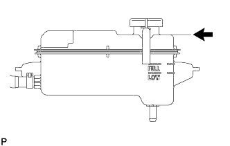
After idling the engine for 10 minutes, add coolant until it reaches the B line.
Capacity Approximately 2.5 to 3.5 liters (2.6 to 3.7 US qts, 2.2 to 3.1 Imp. qts) Text in Illustration B Line Tech Tips
The B line is the lower edge of the inner wall of the filler neck.
-
Close the radiator reservoir cap, and run the engine at 1500 to 2000 rpm for 5 minutes.
CAUTION:
-
Wear protective gloves.
-
Be careful as the radiator hoses are hot.
-
Keep your hands away from the radiator fans.
Tech Tips
The thermostat open timing can be confirmed by pressing the No. 1 radiator hose by hand, and checking when the SLLC starts to flow inside the hose.
-
-
-
Stop the engine and wait until the coolant cools down to ambient temperature.
-
Check the coolant level.
If the coolant level is below the FULL line, add coolant until it reaches the FULL line.
-
-
ADD AUTOMATIC TRANSMISSION FLUID
-
CONNECT CABLE TO NEGATIVE BATTERY TERMINAL
Note
When disconnecting the cable, some systems need to be initialized after the cable is reconnected Click here.
-
INSPECT FOR OIL LEAK
-
Start the engine. Make sure that there are no oil leaks from the area that was worked on.
-
-
INSPECT FOR COOLANT LEAK
CAUTION:
Do not remove the radiator reservoir cap while the engine and radiator are still hot. Pressurized, hot engine coolant and steam may be released and cause serious burns.
Note
Before each inspection, turn the A/C switch OFF.
-
Fill the radiator with coolant and attach a radiator cap tester.
-
Warm up the engine.
-
Using the radiator cap tester, increase the pressure inside the radiator to 118 kPa (1.2 kgf/cm2, 17 psi), and check that the pressure does not drop.
If the pressure drops, check the hoses, radiator and water pump for leaks. If no external leaks are found, check the heater core, cylinder block and head.
-
-
INSPECT FOR FUEL LEAK
-
Connect the intelligent tester to the DLC3.
-
Turn the engine switch on (IG).
Note
Do not start the engine.
-
Turn the intelligent tester on.
-
Select the following menus: Powertrain / Engine / Active Test / Control the Fuel Pump / Speed.
-
Check the fuel pump operation.
-
Check for pressure in the fuel inlet tube from the fuel line. Check that the sound of fuel flowing in the fuel tank can be heard.
If no sound can be heard, check the integration relay, fuel pump, ECM and wiring connector.
-
-
Check for fuel leaks.
-
Check that there are no fuel leaks anywhere on the system after performing maintenance.
If there is a fuel leak, repair or replace parts as necessary.
-
-
-
INSPECT FOR EXHAUST GAS LEAK
-
If gas is leaking, tighten the areas necessary to stop the leak. Replace the damaged parts as necessary.
-
-
PLACE FRONT WHEELS FACING STRAIGHT AHEAD
-
CHECK AND ADJUST FRONT WHEEL ALIGNMENT
-
CHECK SHIFT LEVER POSITION
-
INSTALL FRONT SUSPENSION MEMBER PROTECTOR LOWER
-
Install the front suspension member protector lower with the 8 bolts.
- Torque:
- 5.5 N*m { 56 kgf*cm, 49 in.*lbf }
-
-
INSTALL NO. 2 ENGINE UNDER COVER
-
Install the No. 2 engine under cover with the 8 bolts.
- Torque:
- for bolt A
- 10 N*m { 102 kgf*cm, 7 ft.*lbf }
- for bolt B
- 27 N*m { 275 kgf*cm, 20 ft.*lbf }
-
-
INSTALL NO. 1 ENGINE UNDER COVER
-
Install the No. 1 engine under cover with the 13 screws and 7 clips.
-
-
CHECK IGNITION TIMING
-
Warm up and stop the engine.
Tech Tips
A warmed up engine should have an engine coolant temperature of over 80°C (176°F) and an engine oil temperature of 60°C (140°F), and the engine rpm should be stabilized.
-
When using the intelligent tester:
-
Connect the intelligent tester to the DLC3.
-
Start the engine and idle it.
-
Push the intelligent tester main switch on.
-
Enter the following menus: Powertrain / Engine and ECT / Data List / Primary / IGN Advance /
Tech Tips
Refer to the intelligent tester operator's manual for further details.
Standard ignition timing 8 to 18° BTDC @ idle
-
-
When not using the intelligent tester:
-
Remove the V-bank cover.
-
Remove the 5 clips and air cleaner inlet cover.
-
Remove the 5 clips and engine room side cover LH.
-
Remove the 2 bolts and No. 1 air cleaner inlet.
-
Disconnect the air cleaner cap LH.
-
Remove the 2 nuts and air cleaner case LH.
-
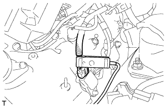
Connect the tester probe of a timing light to the wire of the ignition connector for No. 1 cylinder.
Note
Use a timing light that detects primary signals.
-
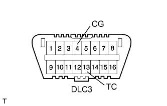
Using SST, connect terminals 13 (TC) and 4 (CG) of the DLC3.
- SST
- 09843-18040
Note
-
Confirm the terminal numbers before connecting them. Connecting the wrong terminals can damage the engine.
-
When checking the ignition timing, the transmission should be in neutral.
-
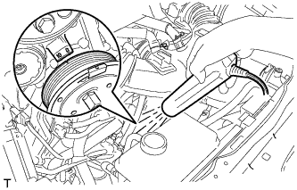
Using a timing light, check the ignition timing.
Standard ignition timing 8 to 12° BTDC @ idle -
Remove SST from the DLC3.
-
Check the ignition timing.
Standard ignition timing 8 to 18° BTDC @ idle -
Check that the ignition timing advances immediately when the engine speed is increased.
-
Disconnect the timing light from the engine.
-
Install the air cleaner case LH with the 2 nuts.
- Torque:
- 5.0 N*m { 51 kgf*cm, 44 in.*lbf }
-
Connect the air cleaner cap LH.
-
Install the No. 1 air cleaner inlet with the 2 bolts.
- Torque:
- 5.0 N*m { 51 kgf*cm, 44 in.*lbf }
-
Install the engine room side cover LH with the 5 clips.
-
Install the air cleaner inlet cover with the 5 clips.
-
Install the V-bank cover.
-
-
-
CHECK IDLE SPEED
-
Warm up and stop the engine.
Tech Tips
A warmed up engine should have an engine coolant temperature of over 80°C (176°F) and an engine oil temperature of 60°C (140°F), and the engine rpm should be stabilized.
-
When using the intelligent tester:
-
Connect the intelligent tester to the DLC3.
Note
Switch off all accessories and the A/C before connecting the intelligent tester.
-
Race the engine at 2500 rpm for approximately 90 seconds.
-
Push the intelligent tester main switch on.
-
Enter the following menus: Powertrain / Engine and ECT / Data List / Primary / Engine Speed
Standard idle speed 700 to 800 rpm Note
When checking the idle speed, the transmission should be in neutral.
Tech Tips
Refer to the intelligent tester operator's manual for further details.
If the idle speed is not as specified, check the air intake system.
-
Disconnect the intelligent tester from the DLC3.
-
-
When not using the intelligent tester:
-
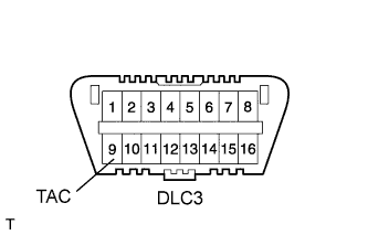
Using SST, connect a tachometer probe to terminal 9 (TAC) of the DLC3.
- SST
- 09843-18030
Note
Confirm the terminal numbers before connecting them. Connecting the wrong terminals can damage the engine.
-
Race the engine speed at 2500 rpm for approximately 90 seconds.
-
Check the idle speed.
Idle speed (Transmission neutral position) 700 to 800 rpm If the speed is not as specified, check the air intake system.
-
Disconnect the tachometer from the DLC3.
-
-
-
CHECK CO/HC
Tech Tips
This check determines whether or not the idle CO/HC complies with regulations.
-
Start the engine.
-
Keep the engine speed at 2500 rpm for approximately 180 seconds.
-
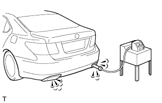
Insert the CO/HC meter testing probe at least 40 cm (1.31 ft) into the tailpipe during idling.
-
Immediately check CO/HC concentration at idle and 2500 rpm.
Tech Tips
-
When performing the 2 mode (2500 rpm and idle) test, follow the measurement order prescribed by the applicable local regulations.
-
If the CO/HC concentration does not comply with regulations, troubleshoot in the order given below.
-
Check the air fuel ratio sensor Click here and heated oxygen sensor Click here operation.
-
See the table below for possible causes, and then inspect and correct the applicable causes if necessary.
CO HC Symptom Causes Normal High Rough idle
-
1. Faulty ignitions
-
Incorrect timing
-
Plugs are contaminated, shorted, or gaps are defective.
-
2. Leaky intake and exhaust valves
-
3. Leaky cylinder
Low High Rough idle
(Fluctuating HC reading)
-
1. Vacuum leaks
-
PCV hose
-
Intake manifold
-
Throttle body
-
2. Lean mixture causing misfire
High High Rough idle
(Black smoke from exhaust)
-
1. Restricted air filter
-
2. Faulty SFI system
-
Faulty pressure
-
Defective engine coolant temperature sensor
-
Faulty ECM
-
Faulty injector
-
Faulty throttle position sensor
-
Faulty mass air flow meter
-
-
-
-
CHECK ENGINE OIL LEVEL
-
Warm up the engine, stop the engine and wait 5 minutes. The oil level should be between the dipstick's low level mark and full level mark.
If low, check for leakage and add oil up to the full level mark.
Note
Do not fill engine oil above the full level mark.
Tech Tips
A certain amount of engine oil will be consumed while driving. In the following situations, oil consumption may increase, and engine oil may need to be refilled in between oil maintenance intervals.
-
When the engine is new, for example directly after purchasing the vehicle or after replacing the engine.
-
If low quality oil or oil of an inappropriate viscosity is used.
-
When driving at high engine speed or with a heavy load, (when towing, or), when driving while accelerating or decelerating frequently.
-
When leaving the idling for a long time, or when driving frequently through heavy traffic.
When judging the amount of oil consumption, keep in mind that the oil may have become diluted, making it difficult to judge the true level accurately.
-
-
-
INSTALL ENGINE ROOM SIDE COVER RH
-
Install the engine room side cover RH with the 5 clips.
-
-
INSTALL ENGINE ROOM SIDE COVER LH
-
Install the engine room side cover LH with the 5 clips.
-
-
INSTALL AIR CLEANER INLET COVER SUB-ASSEMBLY
-
Attach the 4 clips labeled B.
Note
-
Make sure the clips are attached securely.
-
Attaching the clips forcefully or hitting the top of the clips may damage them.
-
-
Install the air cleaner inlet cover sub-assembly with the 5 clips labeled A.
-
-
INSTALL V-BANK COVER SUB-ASSEMBLY
-
Slide the cover from the vehicle front toward the rear of the vehicle to attach the 2 clips labeled A, and then attach the 4 clips labeled B to install the V bank cover sub-assembly.
Note
-
Make sure the clips are attached securely.
-
Attaching the clips forcefully or hitting the top of the clips may damage them.
-
When attaching the clips labeled A, be sure to slide the cover from the front of the vehicle toward the rear of the vehicle.
-
-
-
INSTALL COWL TOP VENTILATOR LOUVER
-

for LHD:
Install the 6 clips and cowl top ventilator louver RH.
Note
If the cowl top ventilator louver RH is not properly installed, water may leak into the engine room and cause malfunctions. Therefore, make sure the cowl top ventilator louver RH is installed properly.
-

for RHD:
Install the 6 clips and cowl top ventilator louver LH.
Note
If the cowl top ventilator louver LH is not properly installed, water may leak into the engine room and cause malfunctions. Therefore, make sure the cowl top ventilator louver LH is installed properly.
-