ECD SYSTEM (w/o DPF) Engine Difficult to Start or Stalling
DESCRIPTION
-
Faults and Symptoms of Common Rail Diesel Components
-
Engine Control
Mass Air Flow Meter Main fault Decrease in performance (foreign matter is stuck) Symptoms Lack of power, black smoke Data List MAF Tech Tips
The maximum fuel injection volume is controlled according to the output from the mass air flow meter.
Intake System Symptom and Corresponding Main Fault
-
Lack of power (no black smoke) due to air filter blockage or crushed or leaking air duct
-
Black smoke (no lack of power) due to leakage between the turbo and intake manifold
Data List MAP Turbocharger System Main fault
-
Air leak in the turbocharged air passage
-
ECM not operating well
-
Turbocharger (turbine, bearing)
Symptoms Lack of power (when vehicle is starting, under heavy load)
(Black smoke is not emitted when racing while vehicle is stopped)
Data List MAP
-
With the ignition switch ON or during idling, MAP = atmospheric pressure (standard atmospheric pressure = 101 kPa). When the engine speed is about 1500 rpm or more, the turbocharger starts to take effect and MAP becomes higher than atmospheric pressure.
-
Atmospheric pressure decreases by 1 kPa each time elevation increases by 100 m, and is also affected by the current weather conditions.
Exhaust System Main fault Blockage Symptoms Lack of power (high engine speed, under heavy load) Glow System Main fault Open circuit, glow plug relay fault Symptoms Difficult to start, rough idle, knocking, white smoke (when cold) Data List Check the glow plug indicator light Diagnostic Point Measure the resistance of the glow plug Battery Main fault Battery is depleted Symptoms Difficult to start (cannot crank, crank speed is low), horn is quiet Data List Battery Voltage
When cranking, battery voltage is below 5 V.
Engine - 1 Main fault Damaged, seized up Symptoms Cannot crank, crank speed is low, strange noise Engine - 2 Main fault Loss of compression Symptoms Rough idle (lack of power always) Data List Injection Feedback Val
-
When an Injector Feedback Val is more than 3 mm3/st, there may be a malfunction in the corresponding cylinder.
Start System Main fault Starter system malfunction Symptoms Difficult to start Data List Starter Signal
-
Ignition switch (STA) output:
ON: Starter is operating
OFF: Starter is not operating
-
-
Diesel Injection
Fuel Supply Pump Main fault - Symptoms Difficult to start, engine stalling, rough idle, lack of power Data List Fuel Press, Target Common Rail Pressure
-
Fuel Press is within 5000 kPa of Target Common Rail Pressure during idling with the engine warmed up (engine coolant temperature is higher than 70°C (158°F)).
-
If the fuel pressure is 20000 kPa below the target pressure, then a lack of power will be felt.
-
If the fuel pressure is below 25000 kPa, then idling will be rough.
Tech Tips
The fuel pressure changes at engine start, but is approx. 25000 kPa at engine start after the engine is warmed up.
Diagnostic Trouble Code Even if Fuel Press is below Target Common Rail Pressure, a DTC will not be stored. Fuel Filter Main fault Blockage Symptoms Difficult to start, engine stalling, rough idle, lack of power Data List Fuel Press, Target Common Rail Pressure
-
Fuel Press is within 5000 kPa of Target Common Rail Pressure during idling with the engine warmed up (engine coolant temperature is higher than 70°C (158°F)).
-
If the fuel pressure is 20000 kPa below the target pressure, then a lack of power will be felt.
-
If the fuel pressure is below 25000 kPa, then idling will be rough.
Tech Tips
The fuel pressure changes at engine start, but is approx. 25000 kPa at engine start after the engine is warmed up.
Diagnostic Trouble Code Even if Fuel Press is below Target Common Rail Pressure, a DTC will not be stored. Injector Assembly Main fault Blockage Symptoms Rough idle, lack of power, black smoke, white smoke, knocking Data List Injection Feedback Val
-
When an Injector Feedback Val is more than 3 mm3/st, there may be a malfunction in the corresponding cylinder. This value can be read after idling for 1 minute.
Pressure Discharge Valve Main fault Does not completely close Symptoms Difficult to start, engine stall, rough idle, lack of power Injector Driver Main fault Circuit fault: The injector assembly does not open. Symptoms Difficult to start, rough idle, lack of power, black smoke, white smoke, knocking Data List Same as injector assembly Diagnostic Trouble Code When the injector driver has a fault, some DTCs may be stored. Fuel Pressure Sensor Main fault Open circuit, decrease in performance (foreign matter is stuck) Symptoms Difficult to start, rough idle, engine stall, lack of power Data List Fuel Press, Target Common Rail Pressure
-
Slowly raise the engine speed from idling to 3000 rpm with the vehicle stopped and check that Fuel Press and Common Rail Pres Sens 2 follow Target Common Rail Pressure. If the fuel pressure sensor malfunctions, the actual fuel pressure may deviate from the target fuel pressure (either Fuel Press or Common Rail Pres Sens 2 decreases to a value less than Target Common Rail Pressure).
Diagnostic Trouble Code When the fuel pressure sensor has a fault, some DTCs may be stored. Irregular Fuel Main fault - Symptoms Difficult to start, rough idle (especially when cold) -
-
Diesel EGR
EGR System Main fault
-
Does not move smoothly
-
Does not close completely
Symptoms
-
Rough idle
-
EGR valve stuck closed: A loud turbocharger sound.
-
EGR valve stuck open: Difficult to start (does not stall), black smoke, lack of power (if there is an excess in the quantity of EGR and there is a heavy load, when the vehicle starts moving, a lack of power will be felt).
-
-
Diesel Throttle
Diesel Throttle System Main fault Stuck, does not move smoothly Symptoms
-
Stuck closed: Lack of power, difficult to start, rough idle, engine stall, black smoke. These may occur when stuck almost fully closed.
-
Stuck open: Turbocharger sound increases. When the engine is stopped, engine vibrations may occur.
-
-
-
Data List Related to Starting Trouble
-
MAP
-
MAF
-
Intake Air
-
Coolant Temp
-
Battery Voltage
-
Starter Signal
-
Target Common Rail Pressure
-
Fuel Press
-
Injection Feedback Val #1 (to #4)
-
Injection Volume
-
INSPECTION PROCEDURE
-
Explanation of Symptom
Starting Trouble For good starting it is essential to have:
-
Sufficient cranking speed.
-
Properly operating engine preheating system.
-
Good quality fuel.
The fuel is ignited by the heat which is generated by compression pressure.
With problems such as a depleted battery, the crankshaft speed can become low, or if the engine compression is poor due to leakage, the compression pressure will not rise and there will be difficulty starting.
When the engine is cold, even if there is compression heat, it will escape from the combustion chamber. For this reason, when the engine is started when it is cold, the glow plugs heat the compressed air.
Also, after starting the engine, by charging the glow plugs for a fixed time set according to the engine coolant temperature, diesel knocking and white smoke are prevented. The quantity of fuel injected is determined by the fuel pressure and also the amount of time the injector assembly is open.
-
-
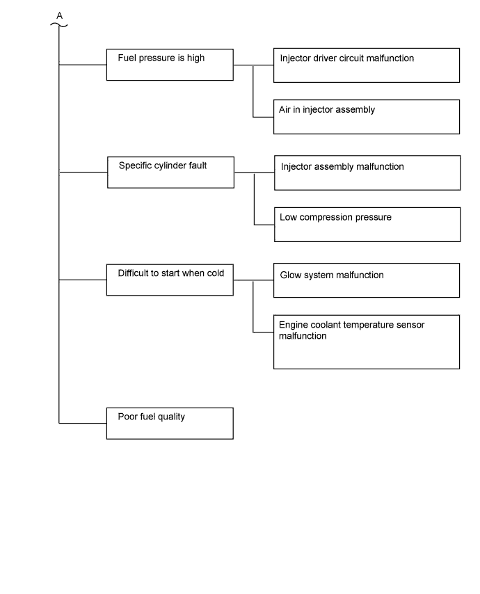
Trouble Area Chart According to Problem Cause
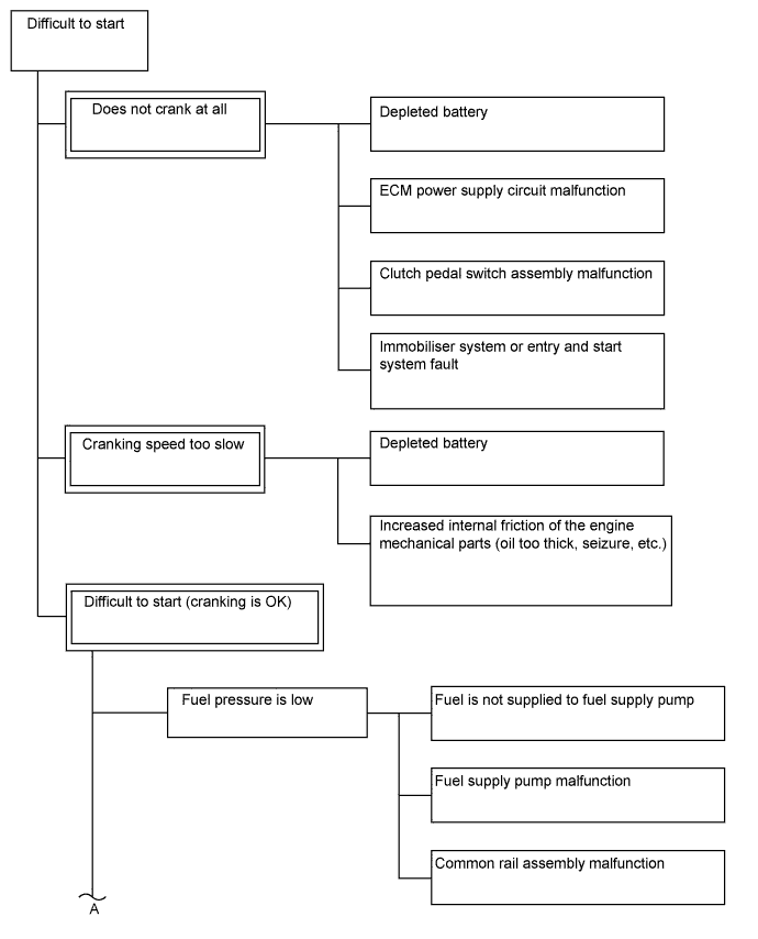
Note
-
After replacing the ECM, the new ECM needs registration Click here and initialization Click here.
-
After replacing the Fuel Supply Pump, the ECM needs initialization Click here.
-
After replacing an injector assembly, the ECM needs registration Click here.
Tech Tips
Specified values in the following troubleshooting flowchart are for reference only. Variations in the Data List values may occur depending on the measuring conditions or the vehicle age. Do not assume the vehicle is normal when the Data List outputs standard values. There may be concealed factors of the malfunction.
-
PROCEDURE
-
CHECK ENGINE CRANKING CONDITION
-
Check the engine cranking condition.
Result Result Proceed to Cranking is OK. A Low cranking speed.
Tech Tips
When cranking speed is low, especially when the temperature is low, check if the engine oil grade matches the recommendation.
B Does not crank at all. C
B 
CHECK BATTERY CONDITION Click here
C 
READ OUTPUT DTC (RELATED TO ENGINE) Click here
A 
-
-
READ ALL OUTPUT DTCS
-
Connect the intelligent tester to the DLC3.
-
Turn the ignition switch to ON and turn the tester on.
-
Enter the following menus: Utility / All Codes.
Result Result Proceed to No DTC is output A DTCs related to engine are output B
B
GO TO RELATED DTC Click here
A
-
-
TAKE SNAPSHOT DURING STARTING AND IDLING (PROCEDURE 3)
-
Connect the intelligent tester to the DLC3.
-
Turn the ignition switch to ON and turn the tester on.
-
Enter the following menus: Powertrain / Engine and ECT / Data List / All Data.
-
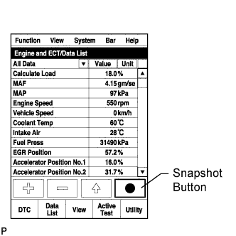
Take a snapshot when idling with no load after the engine is warmed up and when starting trouble is occurring.
Tech Tips
-
A snapshot can be used to compare vehicle data from the time of the malfunction to normal data and is very useful for troubleshooting. The data in the illustration below is that of a normal vehicle, but as the data varies between individual vehicles, this data should only be used for reference.
-
When there is trouble starting with a cold engine, take the snapshot when the engine is cold. Then warm up the engine (engine coolant temperature is 70°C (158°F) or higher) and after idling the vehicle for 1 minute (A/C off, electrical load off), take a snapshot of the data for 15 seconds while idling.
-
Graphs like the ones shown below can be displayed by transferring the stored snapshot from the tester to a PC. Intelligent Viewer must be installed on the PC.
-
Take a snapshot when the problem is occurring, such as when the engine is cold. However, if the problem does not reoccur, it is acceptable to only take a snapshot after the engine is warmed up and when the engine is started.
-
NEXT
-
-
CHECK SNAPSHOT (FUEL PRESS)
-
Check Fuel Press in the snapshot taken in procedure 3 when the engine was started.
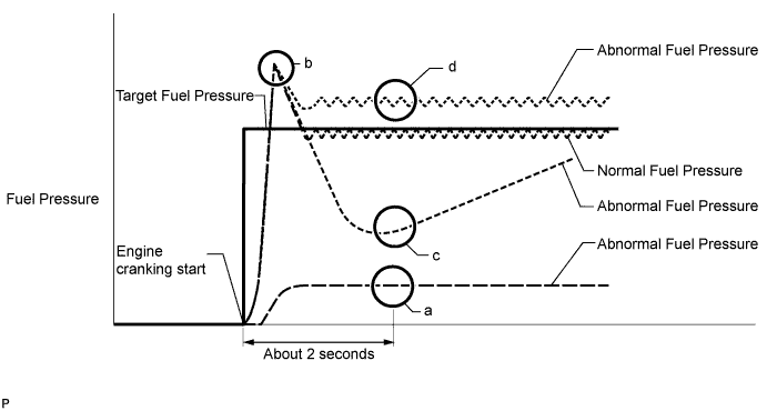
Result Result Proceed to At the point in the illustration labeled "a", Fuel Press is less than 10000 kPa from the value of Fuel Press when cranking started A At the point in the illustration labeled "c", Fuel Press is below Target Common Rail Pressure by 15000 kPa or more B Fuel Press increases to a value that is higher than Target Common Rail Pressure immediately after cranking, and, at the point in the illustration labeled "d", Fuel Press is higher than Target Common Rail Pressure C Except above D Tech Tips
-
Even if Fuel Press is temporarily higher than Target Common Rail Pressure, as shown at the point in the illustration labeled "b", the fuel supply pump is normal.
-
Fuel pressure is about 25000 to 35000 kPa when the engine is cranking and the engine coolant temperature is 0°C (32°F) or higher.
-
Fuel pressure increases rapidly during cranking.
-
B
READ VALUE USING INTELLIGENT TESTER (FUEL PRESS) Click here
C
INSPECT INJECTOR DRIVER (POWER SOURCE) Click here
D
CHECK DATA LIST Click here
A
-
-
CHECK IF FUEL IS BEING SUPPLIED TO FUEL SUPPLY PUMP
-
Disconnect the inlet hose from the Fuel Supply Pump.
-
Operate the priming pump and check that fuel is being supplied to the Fuel Supply Pump.
OK Fuel is properly supplied to the fuel supply pump when the priming pump is operated. Tech Tips
-
When there is a lack of fuel, fuel pressure drops.
-
Inspect for Fuel Filter clogging (check that the Fuel Filter is not clogged).
-
-
Reconnect the inlet hose.
NG
CHECK AND REPAIR OR REPLACE CLOGGED FUEL PIPE (INCLUDING FROZEN FUEL) (FUEL TANK - FUEL SUPPLY PUMP) Click here
OK
-
-
CHECK HARNESS AND CONNECTOR (SUCTION CONTROL VALVE - ECM)
-
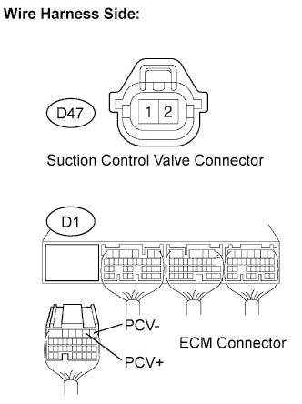
Disconnect the D47 suction control valve connector.
-
Disconnect the D1 ECM connector.
-
Measure the resistance of the wire harness side connector.
Standard resistance (Check for open) Tester Connection Specified Condition D47-1 - PCV+ (D1-2) Below 1 Ω D47-2 - PCV- (D1-1) Standard resistance (Check for short) Tester Connection Specified Condition D47-1 or PCV+ (D1-2) - Body ground 10 kΩ or higher D47-2 or PCV- (D1-1) - Body ground -
Reconnect the ECM connector.
-
Reconnect the suction control valve connector.
NG
REPAIR OR REPLACE HARNESS OR CONNECTOR
OK
-
-
REPLACE SUCTION CONTROL VALVE
-
Replace the suction control valve Click here.
NEXT
-
-
BLEED AIR FROM FUEL SYSTEM
-
Bleed the air from the fuel system Click here.
NEXT
-
-
PERFORM FUEL SUPPLY PUMP INITIALIZATION
-
Perform fuel supply pump initialization Click here.
NEXT
-
-
READ VALUE USING INTELLIGENT TESTER (FUEL PRESS)
-
Connect the intelligent tester to the DLC3.
-
Turn the ignition switch to ON and turn the tester on.
-
Enter the following menus: Powertrain / Engine and ECT / Data List / Fuel Press.
-
Start the engine.
-
Read the Fuel Press values while cranking and idling the engine.
Result Result Proceed to The engine cannot be started or the engine can be started but Fuel Press is below 20000 kPa 2 seconds after the starter signal changes from OFF to ON B Except above A
B
INSPECT INJECTOR ASSEMBLY (INSPECTION FOR VALVE CLOSING PROBLEM) Click here
A 
END
-
-
INSPECT INJECTOR ASSEMBLY (INSPECTION FOR VALVE CLOSING PROBLEM)
-
Remove the glow plug assembly for all the cylinders Click here.
-
Visually check if there is fuel on the glow plugs.
Tech Tips
-
If there is fuel on a glow plug, fuel may be leaking from an injector assembly.
-
After replacing an injector assembly, make sure that the common rail pressure (fuel pressure) is within 5000 kPa of the target fuel pressure while cranking the engine.
-
If there is fuel on a glow plug, fuel may have mixed with the engine oil. Check the engine oil amount and whether the engine oil smells of diesel fuel. If the oil level is above the full line or the engine oil smells of diesel fuel, replace the engine oil.
-
-
Install the glow plug assembly Click here.
NEXT
REPLACE INJECTOR ASSEMBLY OF MALFUNCTIONING CYLINDER Click here
-
-
CHECK AND REPAIR OR REPLACE CLOGGED FUEL PIPE (INCLUDING FROZEN FUEL) (FUEL TANK - FUEL SUPPLY PUMP)
-
Check and repair or replace the clogged fuel pipe.
NEXT
-
-
BLEED AIR FROM FUEL SYSTEM
-
Bleed the air from the fuel system Click here.
NEXT
CONFIRM WHETHER MALFUNCTION HAS BEEN SUCCESSFULLY REPAIRED Click here
-
-
READ VALUE USING INTELLIGENT TESTER (FUEL PRESS)
-
Check Fuel Press in the snapshot taken in procedure 3 when the engine was warmed up.
Result Result Proceed to Fuel Press is more than 5000 kPa from Target Common Rail Pressure A Except above B
B
REPLACE INJECTOR ASSEMBLIES OF ALL CYLINDERS Click here
A
-
-
REPLACE SUCTION CONTROL VALVE
-
Replace the suction control valve Click here.
NEXT
-
-
PERFORM FUEL SUPPLY PUMP INITIALIZATION
-
Perform fuel supply pump initialization Click here.
NEXT
-
-
REPLACE INJECTOR ASSEMBLIES OF ALL CYLINDERS
-
Replace the injector assemblies Click here.
Note
-
When replacing the injector assembly for a cylinder, always be sure to use a new injection pipe.
-
Follow the procedure in the repair manual and temporarily install the injection pipes and nozzle leakage pipe, and then correctly position the injector assemblies. After that, tighten parts according to the torque specifications.
-
If the installation procedure is not performed correctly, injector assemblies may become out of position, which may cause the injector assemblies to deteriorate, resulting in malfunctions.
-
If an injector assembly deteriorates and malfunctions, other problems such as knocking, rough idle, etc. may occur.
-
If an injector assembly becomes out of position, it is possible that the seal between the injector assembly and injection pipe may become incomplete, resulting in a fuel leak.
-
NEXT
CLEAN FUEL FILTER CASE AND REPLACE FUEL FILTER Click here
-
-
CHECK DATA LIST
-
Check Injection Feedback Val # in the snapshot taken in procedure 3 when the engine was idling.
Result Result Proceed to Injection Feedback Val #1 to #4 are 3 mm3/st or less.
Injection Volume is more than 12 mm3/st.
A* Injection Feedback Val for at least one cylinder is more than +3 mm3/st
Tech Tips
There may be a malfunction in the corresponding cylinder.
B Except above C Tech Tips
-
*: When this case occurs, usually symptoms may be noticeable, such as difficulty starting, lack of power.
-
The shift lever should be in neutral and the A/C switch and all accessory switches should be off.
-
B
CHECK CYLINDER COMPRESSION PRESSURE Click here
C
INSPECT INJECTOR ASSEMBLY Click here
A
-
-
REPLACE INJECTOR ASSEMBLIES OF ALL CYLINDERS
-
Replace the injector assemblies Click here.
Note
-
When replacing the injector assembly for a cylinder, always be sure to use a new injection pipe.
-
Follow the procedure in the repair manual and temporarily install the injection pipes and nozzle leakage pipe, and then correctly position the injector assemblies. After that, tighten parts according to the torque specifications.
-
If the installation procedure is not performed correctly, injector assemblies may become out of position, which may cause the injector assemblies to deteriorate, resulting in malfunctions.
-
If an injector assembly deteriorates and malfunctions, other problems such as knocking, rough idle, etc. may occur.
-
If an injector assembly becomes out of position, it is possible that the seal between the injector assembly and injection pipe may become incomplete, resulting in a fuel leak.
-
NEXT
CLEAN FUEL FILTER CASE AND REPLACE FUEL FILTER Click here
-
-
CHECK CYLINDER COMPRESSION PRESSURE
-
Check the cylinder compression pressure Click here.
Tech Tips
When compression is low, there may be cracks in the piston or the injector may be installed improperly.
NG
CHECK ENGINE TO DETERMINE CAUSE OF LOW COMPRESSION
OK
-
-
REPLACE INJECTOR ASSEMBLY OF MALFUNCTIONING CYLINDER
Tech Tips
It can be determined that the injector assembly is faulty as the corresponding cylinder is malfunctioning, but has no compression loss.
-
Replace the injector assembly Click here.
Note
-
When replacing the injector assembly for a cylinder, always be sure to use a new injection pipe.
-
Follow the procedure in the repair manual and temporarily install the injection pipes and nozzle leakage pipe, and then correctly position the injector assemblies. After that, tighten parts according to the torque specifications.
-
If the installation procedure is not performed correctly, injector assemblies may become out of position, which may cause the injector assemblies to deteriorate, resulting in malfunctions.
-
If an injector assembly deteriorates and malfunctions, other problems such as knocking, rough idle, etc. may occur.
-
If an injector assembly becomes out of position, it is possible that the seal between the injector assembly and injection pipe may become incomplete, resulting in a fuel leak.
-
NEXT
-
-
CLEAN FUEL FILTER CASE AND REPLACE FUEL FILTER
-
Clean the fuel filter case and replace the fuel filter.
Tech Tips
Be sure to clean the inside of the fuel filter case as the fuel injectors may not operate properly if the fuel filter is installed with foreign matter remaining inside the fuel filter case.
NEXT
-
-
BLEED AIR FROM FUEL SYSTEM
-
Bleed the air from the fuel system Click here.
NEXT
-
-
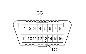
PERFORM ECM INITIALIZATION AND REGISTER INJECTOR COMPENSATION CODE
-
Perform the ECM initialization.
-
Connect terminals 13 (TC) and 4 (CG) of the DLC3.
-
Turn the ignition switch to ON for 50 minutes or more.
Note
-
Perform ECM initialization only when the injectors for all the cylinders have been replaced.
-
It is necessary to wait for 50 minutes or more. Otherwise, ECM initialization is not completed.
-
-
Turn the ignition switch off.
-
Disconnect terminals 13 (TC) and 4 (CG).
-
-
Register the injector compensation codes Click here.
NEXT
-
-
CONFIRM WHETHER MALFUNCTION HAS BEEN SUCCESSFULLY REPAIRED
NEXT
END
-
INSPECT INJECTOR DRIVER (POWER SOURCE)
-
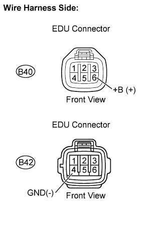
Disconnect the B40 and B42 EDU connectors.
-
Turn the ignition switch to ON.
-
Measure the voltage between the terminals of the EDU connectors.
Standard voltage Tester Connection Specified Condition +B (B40-6) - GND (B42-4) 11 to 14 V -
Reconnect the EDU connectors.
NG
REPAIR OR REPLACE HARNESS OR CONNECTOR
OK
-
-
INSPECT INJECTOR ASSEMBLY
Tech Tips
If there is no initial combustion during cranking, there may be air in the injector assemblies.
NEXT
-
CHECK TEMPERATURE WHEN STARTING TROUBLE OCCURS
-
Check the temperature when starting trouble occurs.
Result Result Proceed to Difficult to start only for cold engine. A Difficult to start both for cold and warmed up engine. B
B
CHECK FUEL QUALITY Click here
A
-
-
READ VALUE USING ENGINE COOLANT TEMPERATURE SENSOR (COOLANT TEMP)
-
Connect the intelligent tester to the DLC3.
-
Turn the ignition switch to ON and turn the tester on.
-
Enter the following menus: Powertrain / Engine and ECT / Data List / All Data / Coolant Temp.
-
Read the value displayed on the tester.
OK Coolant Temp is not high when the engine is cold, and not low after the engine is warmed up
NG
INSPECT ENGINE COOLANT TEMPERATURE SENSOR Click here
OK
-
-
INSPECT GLOW PLUG ASSEMBLY (RESISTANCE)
-
Inspect the glow plug Click here.
NG
REPLACE GLOW PLUG ASSEMBLY Click here
OK
-
-
CHECK FUEL QUALITY
-
Check that only diesel fuel is being used.
-
Check that the fuel does not contain any impurities.
NEXT
CONFIRM WHETHER MALFUNCTION HAS BEEN SUCCESSFULLY REPAIRED Click here
-
-
READ OUTPUT DTC (RELATED TO ENGINE)
-
Connect the intelligent tester to the DLC3.
-
Turn the ignition switch to ON and turn the tester on.
-
Enter the following menus: Powertrain / Engine and ECT / DTC.
-
Read the DTCs.
Result Result Proceed to No DTC is output A DTCs related to engine are output B
B
GO TO RELATED DTC Click here
A
-
-
CHECK COMMUNICATION BETWEEN INTELLIGENT TESTER AND ECM
-
Connect the intelligent tester to the DLC3.
-
Turn the ignition switch to ON and turn the tester on.
-
Check if the normal starting screen appears (check whether communication with the ECM is possible).
Tech Tips
Use a tester that is able to communicate with other vehicles.
OK Communication is possible (vehicle can be recognized).
NG
CHECK VC OUTPUT CIRCUIT Click here
OK
-
-
READ VALUE USING INTELLIGENT TESTER (STARTER SIGNAL)
-
Connect the intelligent tester to the DLC3.
-
Turn the ignition switch to ON and turn the tester on.
-
Enter the following menus: Powertrain / Engine and ECT / Data List / All Data / Starter Signal.
-
Read the value displayed on the tester.
OK Tester Display Condition Specified Condition Starter Signal Cranking ON
NG
GO TO PROBLEM SYMPTOMS TABLE Click here
OK
-
-
CHECK STARTING SYSTEM
-
Inspect the starting system.
Tech Tips
Be sure to inspect the following areas:
-
Starter relay
-
Starter
-
Immobiliser system
-
NEXT
-
-
CONFIRM WHETHER MALFUNCTION HAS BEEN SUCCESSFULLY REPAIRED
NEXT
END