CAUTION / NOTICE / HINT
The necessary procedures (adjustment, calibration, initialization or registration) that must be performed after parts are removed, installed or replaced during the rear seat reclining adjuster sub-assembly removal/installation are shown below.
| Replacement Part or Procedure | Necessary Procedures | Effects / Inoperative when not Performed | Link |
|---|---|---|---|
| Disconnect cable from negative (-) auxiliary battery terminal | Memorize steering angle neutral point | LKA/LDA system (for Mono camera type) | for Stereo Camera type:Click here for Mono Camera type:Click here |
| Lane control system (for Stereo camera type) | |||
| Parking support brake system* | |||
| Pre-collision system (for Mono camera type) | |||
| Pre-collision system (for Stereo camera type) | |||
| Adaptive high beam system | |||
|
|||
| Variable gear ratio steering system | |||
| Parking assist monitor system | |||
| Panoramic view monitor system | |||
| Initialize rear door sunshade system | Rear door sunshade system | ||
| Initialize power trunk lid system | Power trunk lid system | ||
|
Initialize position control ECU | Rear power seat control system |
-
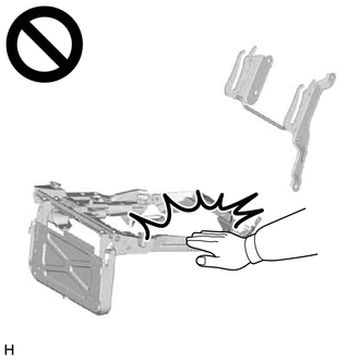
Wear protective gloves. Sharp areas on the parts may injure your hands.
-
There is risk of injury.
-
If the rear seat cushion airbag assembly LH was deployed, replace the rear seat cushion panel LH, rear seat cushion pad and separate type rear seat cushion cover with the necessary parts in accordance with the extent of the collision damage.
-
If the rear seat airbag assembly LH was deployed, replace the rear seat sub panel sub-assembly LH, separate type rear seatback pad and separate type rear seatback cover with the necessary parts in accordance with the extent of the collision damage.
-
Replace any other damaged parts as necessary.
-
Use the same procedure for RHD and LHD vehicles.
-
The procedure listed below is for LHD vehicles.
PROCEDURE
- Click here
REMOVE LUGGAGE COMPARTMENT MAT SUB-ASSEMBLY
- Click here
DISCONNECT CABLE FROM NEGATIVE AUXILIARY BATTERY TERMINAL
-
Disconnect the cable from the negative (-) auxiliary battery terminal.
CAUTION: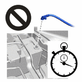
-
Wait at least 90 seconds after disconnecting the cable from the negative (-) auxiliary battery terminal to disable the SRS system.
-
SRS parts are equipped with a backup power source. If work is started within 90 seconds of turning the power switch off and disconnecting the cable from the negative (-) auxiliary battery terminal, SRS parts may deploy.
Note:After turning the power switch off, waiting time may be required before disconnecting the cable from the negative (-) auxiliary battery terminal.
-
-
- Click here
REMOVE REAR SEAT CUSHION ASSEMBLY LH
- Click here
REMOVE REAR SEAT CUSHION ASSEMBLY RH
Tip:Use the same procedure described for the LH side.
- Click here
REMOVE REAR SEATBACK ASSEMBLY LH
- Click here
REMOVE REAR SEATBACK ASSEMBLY RH
- Click here
REMOVE REAR SEAT CUSHION LOCK HOOK
- Click here
REMOVE REAR NO. 2 SEAT ADJUSTER ASSEMBLY
- Click here
REMOVE REAR NO. 1 SEAT ADJUSTER ASSEMBLY
- Click here
REMOVE REAR CENTER SEAT LAP TYPE BELT ASSEMBLY RH
- Click here
REMOVE REAR SEAT INNER BELT ASSEMBLY LH
- Click here
REMOVE REAR SEAT INNER BELT ASSEMBLY RH
- Click here
REMOVE REAR NO. 2 SEAT WIRE LH
- Click here
REMOVE REAR SEAT LEGREST ASSEMBLY
- Click here
REMOVE REAR SEAT LEGREST COVER
- Click here
REMOVE REAR SEAT LEGREST COVER RH (w/ Ottoman)
- Click here
REMOVE REAR SEAT LEGREST COVER (w/ Ottoman)
- Click here
REMOVE REAR NO. 2 SEAT WIRE RH (w/ Ottoman)
- Click here
REMOVE REAR SEAT RECLINING ADJUSTER SUB-ASSEMBLY LH
-
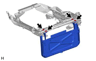
Remove the 4 bolts and rear seat reclining adjuster sub-assembly LH.
-
- Click here
REMOVE REAR SEAT RECLINING ADJUSTER SUB-ASSEMBLY RH
-
w/o Ottoman:
-
Use the same procedure described for the LH side.
-
-
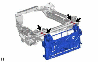
w/ Ottoman:
-
Remove the 4 bolts and rear seat reclining adjuster sub-assembly RH.
-
-