FRONT SEAT ASSEMBLY REMOVAL
CAUTION / NOTICE / HINT
The necessary procedures (adjustment, calibration, initialization or registration) that must be performed after parts are removed, installed or replaced during the front seat assembly removal/installation are shown below.
| Replacement Part or Procedure | Necessary Procedures | Effects / Inoperative when not Performed | Link |
|---|---|---|---|
| Disconnect cable from negative (-) auxiliary battery terminal | Memorize steering angle neutral point | LKA/LDA system (for Mono camera type) | for Stereo Camera type: Click here for Mono Camera type: Click here |
| Lane control system (for Stereo camera type) | |||
| Parking support brake system* | |||
| Pre-collision system (for Mono camera type) | |||
| Pre-collision system (for Stereo camera type) | |||
| Adaptive high beam system | |||
Lighting system (EXT) |
|||
| Variable gear ratio steering system | |||
| Parking assist monitor system | |||
| Panoramic view monitor system | |||
| Initialize rear door sunshade system | Rear door sunshade system | ||
| Initialize power trunk lid system | Power trunk lid system | ||
|
Initialize position control ECU | Front Power Seat Control System | |
| for Front Passenger Side with Occupant Detection System:
|
Zero point calibration (Occupant classification system) |
|
Click here Click here
CAUTION:
-
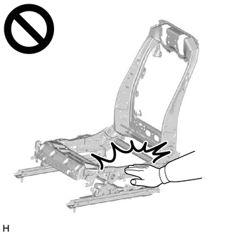
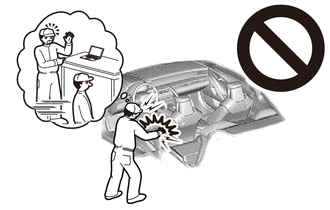
Wear protective gloves. Sharp areas on the parts may injure your hands.
-
There is risk of injury.
Note
-
If the front seat airbag assembly LH was deployed, replace the front seat airbag assembly LH, front seatback frame sub-assembly LH, separate type front seatback pad, separate type front seatback cover with the necessary parts in accordance with the extent of the collision damage.
-
Replace any other damaged parts as necessary.
Tech Tips
-
Use the same procedure for RHD and LHD vehicles.
-
The procedure listed below is for LHD vehicles.
-
Use the same procedure for the RH side and LH side.
-
The following procedure is for the LH side.
PROCEDURE
-
PRECAUTION
CAUTION:
Some of these service operations affect the SRS airbag system. Read the precautionary notices concerning the SRS airbag system before servicing.
Note
After turning the power switch off, waiting time may be required before disconnecting the cable from the negative (-) auxiliary battery terminal. Therefore, make sure to read the disconnecting the cable from the negative (-) auxiliary battery terminal notices before proceeding with work.
-
REMOVE LUGGAGE COMPARTMENT MAT SUB-ASSEMBLY
-
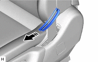
REMOVE FRONT SEATBACK BOARD COVER SUB-ASSEMBLY (w/ Rear Seat Entertainment System)
-

Remove in this Direction 
Place Hand Here Place your hand at the position shown in the illustration and pull toward you to detach the clips and remove the front seatback board cover sub-assembly.
-
-
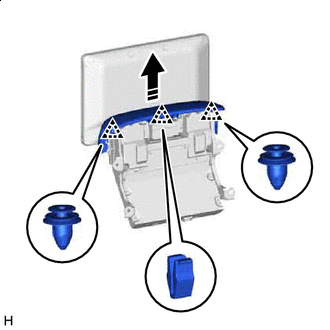
REMOVE TELEVISION DISPLAY ASSEMBLY (w/ Rear Seat Entertainment System)
-
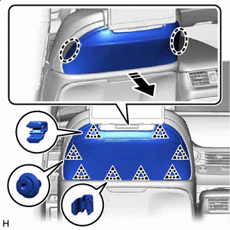
REMOVE FRONT NO. 2 SEATBACK BOARD COVER (w/ Rear Seat Entertainment System)
-
Remove in this Direction Pull in removal direction shown in the illustration to detach the clip and remove the front No. 2 seatback board cover.
-
-
REMOVE FRONT SEAT BELT HOLE COVER LH
-
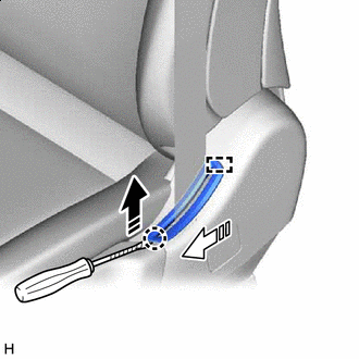
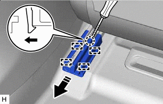
Remove in this Direction (1) 
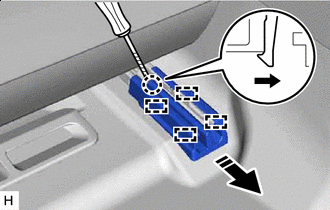
Remove in this Direction (2) 
Protective Tape Using a thin-bladed screwdriver with its tip wrapped with protective tape, lift up in the removal direction (1) shown in the illustration to detach the claw.
-
Pull in removal direction (2) shown in the illustration to detach the guide.
-
Remove in this Direction Slide in the removal direction shown in the illustration and pull the front seat outer belt assembly LH out from the slit of the front seat belt hole cover LH to remove the front seat belt hole cover LH.
-
-
REMOVE SEAT BELT ANCHOR COVER CAP LH
-
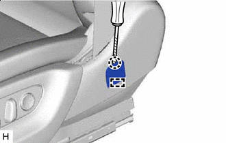
Protective Tape Using a thin-bladed screwdriver with its tip wrapped in protective tape, detach the claw.
-
Detach the guide and remove the seat belt anchor cover cap LH.
-
-
REMOVE FRONT SEAT OUTER BELT ASSEMBLY LH
-
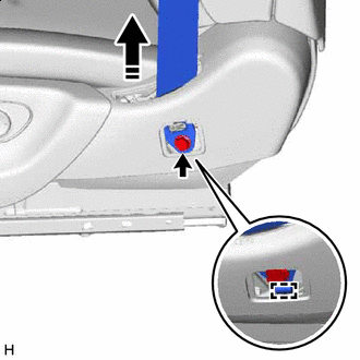
Remove in this Direction Remove the bolt.
-
Detach the hook and pull the front seat outer belt assembly LH out through the hole in the front seat cushion shield LH to remove it.
-
-
REMOVE FRONT OUTER SEAT TRACK BRACKET COVER
Tech Tips
Use the same procedure described for the inner side.
-
Operate the slide and vertical power seat switch knob to slide the front seat assembly LH to the rearmost position.
-
Place Hand Here Remove in this Direction (1) Remove in this Direction (2) Place your hand at the position shown in the illustration and pull in the removal direction (1) to detach the claws.
-
Slide in the removal direction (2) shown in the illustration, detach the guides and remove the front outer seat track bracket cover.
-
-
REMOVE FRONT SEAT LEG COVER (w/ Front Passenger Side Folding Headrest)
Tech Tips
Use the same procedure for the other locations.
-
Remove in this Direction Using moulding remover A, detach the claws.
-
Pull in the removal direction shown in the illustration, detach the guides and remove the front seat leg cover.
-
-
REMOVE OUTER SEAT TRACK COVER RH
-
Operate the slide and vertical power seat switch knob to slide the rear seat assembly LH to the rearmost position.
-
Remove in this Direction Protective Tape Using a thin-bladed screwdriver with its tip wrapped in protective tape, detach the claw.
-
Slide in the removal direction shown in the illustration, detach the guides and remove the outer seat track cover RH.
-
-
REMOVE REAR INNER SEAT TRACK BRACKET COVER LH
-
Remove in this Direction Protective Tape Using a thin-bladed screwdriver with its tip wrapped in protective tape, detach the claw.
-
Pull in the removal direction shown in the illustration, detach the guides and remove the rear inner seat track bracket cover LH.
-
-
REMOVE FRONT SEAT ASSEMBLY
-
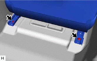
Using a T50 "TORX" socket wrench, remove the 2 TORX screws.
-
Operate the slide and vertical power seat switch knob to slide the front seat assembly LH to the rearmost position.
-
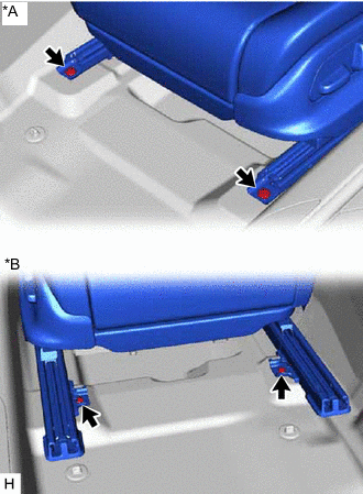
*A for Driver Side *B w/ Front Passenger Side Folding Headrest Using a T50 "TORX" socket wrench, remove the 2 TORX screws.
-
Operate the power seat switch knob to slide the front seat assembly LH to the center position.
-
Operate the reclining power seat switch knob to set the seatback of the front seat assembly LH to the perpendicular position.
-
Operate the slide and vertical power seat switch knob to set the seat cushion height and vertical position of the front seat assembly LH to the lowermost position.
-
Disconnect the cable from the negative (-) auxiliary battery terminal.
CAUTION:
-
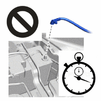
Wait at least 90 seconds after disconnecting the cable from the negative (-) auxiliary battery terminal to disable the SRS system.
-
SRS parts are equipped with a backup power source. If work is started within 90 seconds of turning the power switch off and disconnecting the cable from the negative (-) auxiliary battery terminal, SRS parts may deploy.
Note
After turning the power switch off, waiting time may be required before disconnecting the cable from the negative (-) auxiliary battery terminal.
-
-
Tilt the front seat assembly LH backward.
Note
Do not damage the front seat assembly LH or the interior parts.
-
*A w/ Rear Seat Entertainment System 
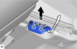
Front Seat Airbag Assembly LH Connector Disconnect the 2 connectors.
-
w/ Rear Seat Entertainment System:
-
Disconnect the 2 connectors.
-
-
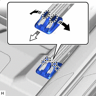
Disconnect the connector of the front seat airbag assembly LH.
-
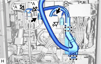
Push down the white housing lock and slide the yellow CPA.
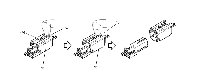
*a Housing Lock *b CPA Note
-
Do not pull while holding the wire harness.
-
Do not try to release the lock while holding down the top of the CPA (A in the illustration), as this prevents the lock from being released.
-
-
Slide the yellow CPA while pushing down the white housing lock again, and disconnect the connector.
-
-
Detach the wire harness protector clamps and disconnect the floor wire.
-
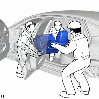
Remove and carry the front seat assembly LH out of the vehicle as shown in the illustration.
Note
-
Carrying the front seat assembly LH from the vehicle must be performed by multiple people.
-
Protect the front seat legs.
-
Do not damage the front seat assembly LH, body exterior or interior parts.
-
-