FRONT FLOOR AIRBAG SENSOR REMOVAL
CAUTION / NOTICE / HINT
The necessary procedures (adjustment, calibration, initialization or registration) that must be performed after parts are removed, installed or replaced during the No. 2 side airbag sensor assembly removal/installation are shown below.
| Replacement Part or Procedure | Necessary Procedures | Effects / Inoperative when not Performed | Link |
|---|---|---|---|
| Disconnect cable from negative (-) auxiliary battery terminal | Memorize steering angle neutral point | LKA/LDA system (for Mono camera type) | for Mono Camera type: for Stereo Camera type: |
| Lane control system (for Stereo camera type) | |||
| Parking support brake system* | |||
| Pre-collision system (for Mono camera type) | |||
| Pre-collision system (for Stereo camera type) | |||
| Adaptive high beam system | |||
Lighting system (EXT) |
|||
| Variable gear ratio steering system | |||
| Parking assist monitor system | |||
| Panoramic View Monitor System | |||
| Initialize rear door sunshade system | Rear door sunshade system | ||
| Initialize power trunk lid system | Power trunk lid system | ||
w/ Occupant Classification System: |
Zero point calibration (Occupant classification system) |
|
Click here Click here
Tech Tips
-
Use the same procedure for RHD and LHD vehicles.
-
The procedure listed below is for LHD vehicles.
-
Use the same procedure for the RH and LH sides.
-
The procedure listed below is for the LH side.
PROCEDURE
-
PRECAUTION
Note
After turning the power switch off, waiting time may be required before disconnecting the cable from the negative (-) auxiliary battery terminal. Therefore, make sure to read the disconnecting the cable from the negative (-) auxiliary battery terminal notices before proceeding with work.
-
REMOVE FRONT SEAT ASSEMBLY LH
-
REMOVE FRONT DOOR SCUFF PLATE LH
-
REMOVE COWL SIDE TRIM BOARD LH
-
REMOVE REAR DOOR SCUFF PLATE LH
-
REMOVE LOWER CENTER PILLAR GARNISH LH
-
REMOVE NO. 2 SIDE AIRBAG SENSOR ASSEMBLY
-
Check that the power switch is off.
-
Check that the cable is disconnected from the negative (-) auxiliary battery terminal.
CAUTION:
-
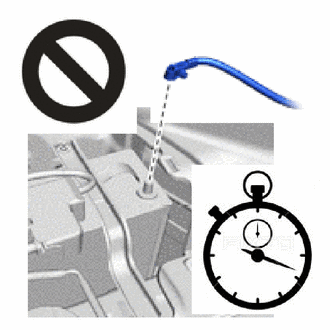
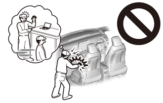
Wait at least 90 seconds after disconnecting the cable from the negative (-) auxiliary battery terminal to disable the SRS system.
-
If this procedure is performed without disconnecting the negative (-) auxiliary battery terminal of the battery, the airbag may deploy even if an impact is applied only to the side airbag sensor assembly LH. Therefore, make sure that the negative (-) auxiliary battery terminal of the battery is disconnected before performing this procedure.
-
-
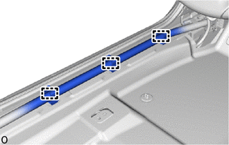
Detach the wire harness clamp.
-
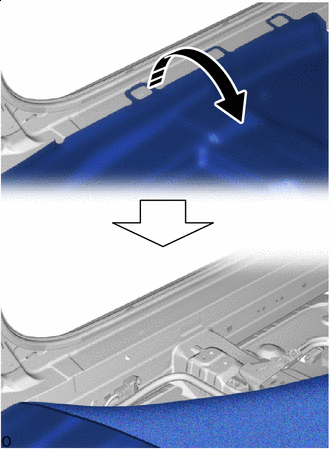

Fold Back Fold back the floor carpet and hold it.
-
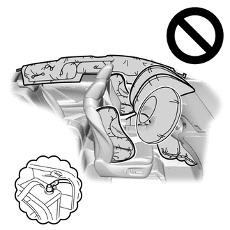
Disconnect the airbag connector.
Note
When disconnecting any airbag connector, take care not to damage the airbag wire harness.
-
Push down the housing lock and slide the CPA. (At this time, the connector cannot be disconnected yet.)
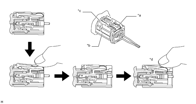
*a Housing Lock *b CPA *c CPA Upper Part *d Connector Lock is Released -
Push the housing lock again and disconnect the connector.
Note
Do not push down the upper part of the CPA shown in the illustration when disconnecting the airbag connector.
-
After disconnecting the connector, check that the position of the housing lock is correct as shown in the illustration.
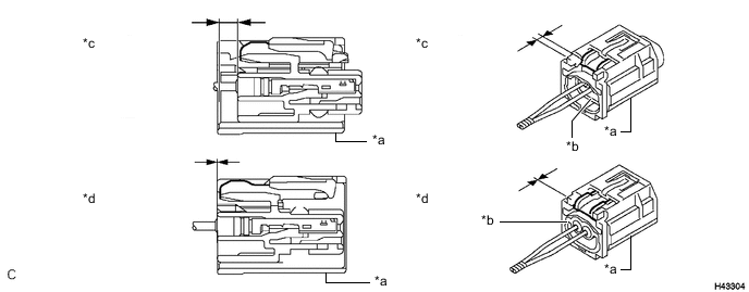
*a CPA *b Housing *c Correct *d Incorrect
-
-
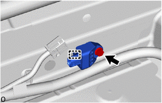
Remove the bolt.
Note
-
Loosen the bolt while holding the No. 2 side airbag sensor assembly LH because the No. 2 side airbag sensor assembly LH guide is easily damaged.
-
If the No. 2 side airbag sensor assembly LH has been dropped, replace it with a new one.
-
-
Detach the guide and remove the No. 2 side airbag sensor assembly LH.
-