DOOR CONTROL RECEIVER REMOVAL
CAUTION / NOTICE / HINT
The necessary procedures (adjustment, calibration, initialization, or registration) that must be performed after parts are removed, installed, or replaced during the door control receiver removal/installation are shown below.
| Replacement Part | Necessary Procedure | Effect/Inoperative Function When Necessary Procedures are not Performed | Link |
|---|---|---|---|
| Removal and installation of auxiliary battery terminal | Memorize steering angle neutral point | LKA/LDA system (for Mono camera type) | for Stereo Camera type: Click here for Mono Camera type: Click here |
| Lane control system (for Stereo camera type) | |||
| Parking support brake system* | |||
| Pre-collision system (for Stereo camera type) | |||
| Pre-collision system (for Mono camera type) | |||
| Adaptive high beam system | |||
Lighting system (EXT) |
|||
| Variable gear ratio steering system | |||
| Parking assist monitor system | |||
| Panoramic view monitor system | |||
| Initialize Rear Door Sunshade System | Rear door sunshade system | ||
| Initialize power trunk lid system | Power trunk lid system | ||
|
|
|
for Initialization: Click here for Registration: Click here |
Click here Click here
PROCEDURE
-
PRECAUTION
Note
After turning the power switch off, waiting time may be required before disconnecting the cable from the negative (-) auxiliary battery terminal. Therefore, make sure to read the disconnecting the cable from the negative (-) auxiliary battery terminal notices before proceeding with work.
-
REMOVE LUGGAGE COMPARTMENT MAT SUB-ASSEMBLY
-
DISCONNECT CABLE FROM NEGATIVE AUXILIARY BATTERY TERMINAL
-
REMOVE LUGGAGE COMPARTMENT FLOOR MAT
-
REMOVE LUGGAGE COMPARTMENT TRIM COVER LH
-
REMOVE LUGGAGE COMPARTMENT TRIM COVER RH
-
REMOVE TOOL BOX
-
REMOVE INNER LOWER LUGGAGE COMPARTMENT TRIM COVER
-
REMOVE FRONT LUGGAGE COMPARTMENT TRIM COVER (w/o Rear Air Conditioning System)
-
INSTALL FRONT LUGGAGE COMPARTMENT TRIM COVER (w/ Rear Air Conditioning System)
Tech Tips
Use the same procedure described for the front luggage compartment trim cover (w/o Rear Air Conditioning System).
-
REMOVE NO. 1 LUGGAGE COMPARTMENT LIGHT ASSEMBLY
-
REMOVE REAR LUGGAGE COMPARTMENT TRIM COVER
-
REMOVE ROPE HOOK ASSEMBLY
-
REMOVE REAR FLOOR FINISH PLATE
-
REMOVE SIDE TRIM BOX
-
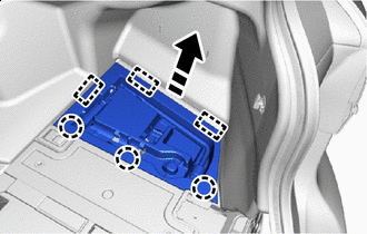

Remove in this Direction Detach the claw and guide and remove the side trim box as shown in the illustration.
-
-
REMOVE LUGGAGE COMPARTMENT TRIM COVER ASSEMBLY RH
-
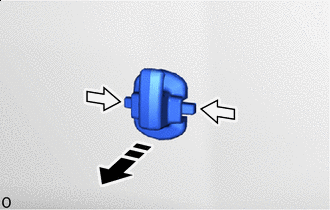
Remove in this Direction 
Push Push the lever in the direction of the arrow shown in the illustration and remove the rope hook.
-
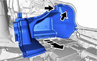
Remove in this Direction 
Clip Grommet Remove the grommet.
-
Using a clip remover, remove the 2 clips and luggage compartment trim cover assembly RH.
-
-
REMOVE ELECTRICAL KEY AND TPMS RECEIVER ASSEMBLY (w/ Tire Pressure Warning System)
-
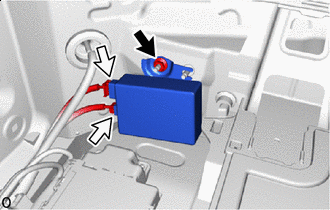
Nut Connector Remove the nut.
-
Disconnect the 2 connectors and remove the electrical key and TPMS receiver assembly.
Note
-
Do not subject the electrical key and TPMS receiver assembly to strong impacts or force, and do not drop it.
-
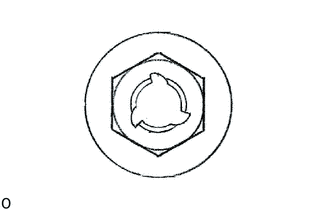
If the removed nut is the same shape as that shown in the illustration, replace it the supplied replacement part.
-
-
-
REMOVE SMART DOOR CONTROL RECEIVER ASSEMBLY (w/o Tire Pressure Warning System)
-
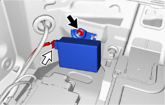
Nut Connector Remove the nut.
-
Disconnect the connector and remove the smart door control receiver assembly.
Note
-
Do not subject the smart door control receiver assembly to strong impacts or force, and do not drop it.
-
If the removed nut is the same shape as that shown in the illustration, replace it the supplied replacement part.
-
-