BATTERY CURRENT SENSOR REMOVAL
CAUTION / NOTICE / HINT
The necessary procedures (adjustment, calibration, initialization or registration) that must be performed after parts are removed and installed, or replaced during battery state sensor assembly removal/installation are shown below.
| Replacement Part or Procedure | Necessary Procedure | Effect/Inoperative Function when Necessary Procedure not Performed | Link |
|---|---|---|---|
| Auxiliary battery terminal is disconnected/reconnected | Memorize steering angle neutral point | LKA/LDA system (for Mono camera type) | for Stereo Camera type: forMono Camera type: |
| Lane control system (for Stereo camera type) | |||
| Parking support brake system* | |||
| Pre-collision system (for Mono camera type) | |||
| Pre-collision system (for Stereo camera type) | |||
| Adaptive high beam system | |||
Lighting system (EXT) |
|||
| Variable gear ratio steering system | |||
| Parking assist monitor system | |||
| Panoramic view monitor system | |||
| Initialize Rear Door Sunshade System | Rear door sunshade system | ||
| Initialize power trunk lid system | Power trunk lid system |
Click here Click here
Note
After the power switch is turned off, the radio receiver assembly records various types of memory and settings. As a result, after turning the power switch off, be sure to wait for the time specified in the following table before disconnecting the cable from the negative (-) auxiliary battery terminal.
| System Name | See Procedure |
|---|---|
| Vehicle enrolled in lexus enform system or safety connect system | 6 minutes |
| Vehicle not enrolled in lexus enform system and safety connect system | 1 minute |
PROCEDURE
-
REMOVE LUGGAGE COMPARTMENT MAT SUB-ASSEMBLY
-
REMOVE TOOL BOX
-
PRECAUTION
Note
After turning the power switch off, waiting time may be required before disconnecting the cable from the negative (-) auxiliary battery terminal. Therefore, make sure to read the disconnecting the cable from the negative (-) auxiliary battery terminal notices before proceeding with work.
-
REMOVE BATTERY STATE SENSOR ASSEMBLY
-
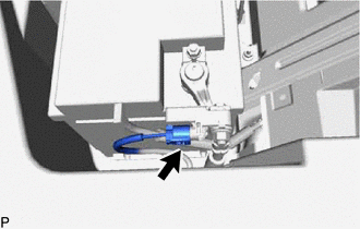
Disconnect the battery state sensor assembly connector.
-
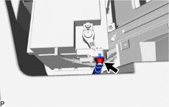
Remove the nut and disconnect the wire harness from the battery state sensor assembly.
Note
When disconnecting the wire harness, some systems need to be initialized after the wire harness is reconnected.
-
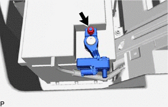
Loosen the nut and remove the battery state sensor assembly from the auxiliary battery.
Note
When disconnecting the wire harness, some systems need to be initialized after the wire harness is reconnected.
-