CAUTION / NOTICE / HINT
The necessary procedures (adjustment, calibration, initialization or registration) that must be performed after parts are removed, installed or replaced during the amplifier antenna removal/installation are shown below.
| Replacement Part or Procedure | Necessary Procedures | Effects / Inoperative when not Performed | Link |
|---|---|---|---|
| Disconnect cable from negative auxiliary battery terminal | Memorize steering angle neutral point | LKA/LDA system (for Mono camera type) | for Stereo Camera type:Click here for Mono Camera type:Click here |
| Lane control system (for Stereo camera type) | |||
| Parking support brake system* | |||
| Pre-collision system (for Mono camera type) | |||
| Pre-collision system (for Stereo camera type) | |||
| Adaptive high beam system | |||
|
|||
| Variable gear ratio steering system | |||
| Parking assist monitor system | |||
| Panoramic view monitor system | |||
| Initialize rear door sunshade system | Rear door sunshade system | ||
| Initialize power trunk lid system | Power trunk lid system |
PROCEDURE
- Click here
PRECAUTION
CAUTION:Note:After turning the power switch off, waiting time may be required before disconnecting the cable from the negative (-) auxiliary battery terminal. Therefore, make sure to read the disconnecting the cable from the negative (-) auxiliary battery terminal notices before proceeding with work.
- Click here
REMOVE LUGGAGE COMPARTMENT MAT SUB-ASSEMBLY
- Click here
DISCONNECT CABLE FROM NEGATIVE AUXILIARY BATTERY TERMINAL
CAUTION: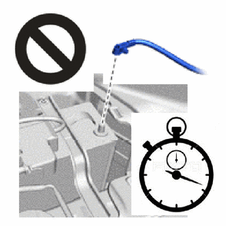
-
Wait at least 90 seconds after disconnecting the cable from the negative (-) auxiliary battery terminal to disable the SRS system.
-
If the airbag deploys for any reason, it may cause a serious accident.
Note:When disconnecting the cable, some systems need to be initialized after the cable is reconnected.
-
- Click here
REMOVE REAR SEAT ASSEMBLY
-
for Fixed Seat Type:
-
for Power Seat:
-
- Click here
REMOVE REAR DOOR SCUFF PLATE LH
- Click here
REMOVE REAR DOOR SCUFF PLATE RH
- Click here
REMOVE REAR SEAT SIDE GARNISH LH
- Click here
REMOVE REAR SEAT SIDE GARNISH RH
- Click here
REMOVE ROOF SIDE RAIL GARNISH ASSEMBLY LH
- Click here
REMOVE ROOF SIDE RAIL GARNISH ASSEMBLY RH
- Click here
REMOVE PACKAGE TRAY TRIM GARNISH LH
- Click here
REMOVE PACKAGE TRAY TRIM GARNISH RH
- Click here
REMOVE PACKAGE TRAY TRIM SIDE COVER LH
- Click here
REMOVE PACKAGE TRAY TRIM SIDE COVER RH
- Click here
REMOVE INNER ROOF SIDE GARNISH ASSEMBLY LH
- Click here
REMOVE INNER ROOF SIDE GARNISH ASSEMBLY RH
- Click here
REMOVE NO. 1 AMPLIFIER ANTENNA ASSEMBLY
-
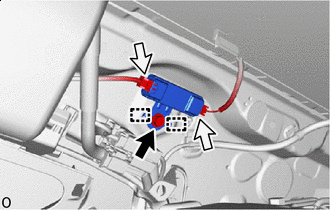

Bolt 
Connector Disconnect the 2 connectors.
-
Remove the bolt.
-
Detach the guide and remove the No. 1 amplifier antenna assembly.
-
- Click here
REMOVE NO. 2 AMPLIFIER ANTENNA ASSEMBLY
-
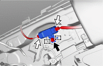
Bolt Connector Disconnect the 2 connectors.
-
Remove the bolt.
-
Detach the guide and remove the No. 2 amplifier antenna assembly.
-