CAUTION / NOTICE / HINT
The necessary procedures (adjustment, calibration, initialization, or registration) that must be performed after parts are removed, installed, or replaced during the tilt and telescopic manual switch removal/installation are shown below.
| Replacement Part or Procedure | Necessary Procedure | Effect/Inoperative when not Performed | Link |
|---|---|---|---|
| Disconnect cable from negative auxiliary battery terminal | Memorize steering angle neutral point | LKA/LDA system (for Mono camera type) | for Stereo Camera type:Click here for Mono Camera type:Click here |
| Lane control system (for Stereo camera type) | |||
| Parking support brake system* | |||
| Pre-collision system (for Mono camera type) | |||
| Pre-collision system (for Stereo camera type) | |||
| Adaptive high beam system | |||
|
|||
| Variable gear ratio steering system | |||
| Parking assist monitor system | |||
| Panoramic view monitor system | |||
| Initialize rear door sunshade system | Rear door sunshade system | ||
| Initialize power trunk lid system | Power trunk lid system |
-
Use the same procedure for RHD and LHD vehicles.
-
The procedure listed below is for LHD vehicles.
PROCEDURE
- Click here
PRECAUTION
Note:After turning the power switch off, waiting time may be required before disconnecting the cable from the negative (-) auxiliary battery terminal. Therefore, make sure to read the disconnecting the cable from the negative (-) auxiliary battery terminal notices before proceeding with work.
- Click here
CUSTOMIZE POWER TILT AND POWER TELESCOPIC STEERING COLUMN SYSTEM
-
Disable the auto tilt away function by changing the customize settings.
Note:Record the current customize setting (whether the auto tilt away function is enabled or disabled) in order to restore the current setting after finishing the operation.
Tip:Performing the above operation causes the auto tilt away function to be disabled when the power switch is turned off.
-
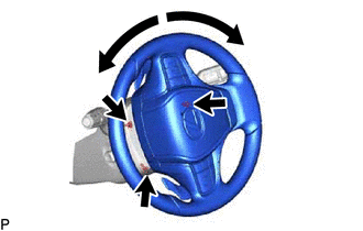
Turn the power switch on (IG). Operate the tilt and telescopic switch to fully extend and lower the steering column assembly.
-
- Click here
REMOVE LUGGAGE COMPARTMENT MAT SUB-ASSEMBLY
- Click here
DISCONNECT CABLE FROM NEGATIVE AUXILIARY BATTERY TERMINAL
Note:When disconnecting the cable, some systems need to be initialized after the cable is reconnected.
- Click here
REMOVE LOWER STEERING COLUMN COVER
-
Remove the 3 screws.
-
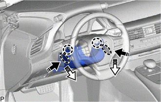

Push Area 
Remove in this Direction (1) 
Remove in this Direction (2) Press in, in the direction shown by the arrow (1) in the illustration, and disengage the claws.
-
Pull out in the direction indicated by the arrow (2) in the illustration, disengage the claws to remove the lower steering column cover.
-
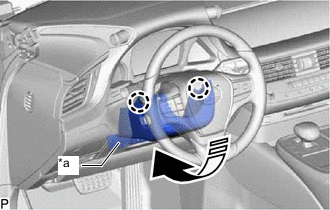
*a Felt 
Remove in this Direction Disengage the 2 claws.
-
Pull in the direction indicated by the arrow to remove the lower steering column cover sub-assembly.
Note:Do not damage the tilt and telescopic switch and felt.
-
- Click here
REMOVE TILT AND TELESCOPIC SWITCH
-
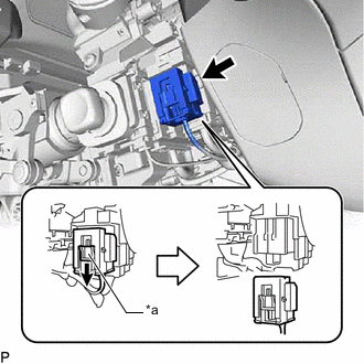
*a Slider Slide the slider to release the lock, and then disconnect the yellow airbag connector from the spiral cable with sensor sub-assembly.
Note:When disconnecting any airbag connector, take care not to damage the airbag wire harness.
-
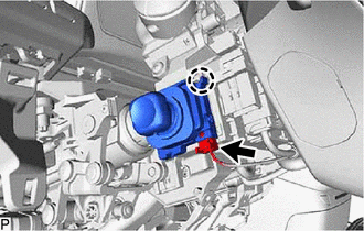
Disconnect the tilt and telescopic connector from the tilt and telescopic switch.
-
Disengage the claw and pull out the tilt and telescopic switch.
-