DYNAMIC REAR STEERING ACTUATOR REMOVAL

CAUTION / NOTICE / HINT
The necessary procedures (adjustment, calibration, initialization, or registration) that must be performed after parts are removed, installed, or replaced during the rear steering link assembly removal/installation are shown below.
| Replacement Part or Procedure | Necessary Procedure | Effect/Inoperative when not Performed | Link |
|---|---|---|---|
| Disconnect cable from negative auxiliary battery terminal | Memorize steering angle neutral point | LKA/LDA system (for Mono camera type) | for Stereo Camera type: Click here for Mono Camera type: Click here |
| Lane control system (for Stereo camera type) | |||
| Parking support brake system* | |||
| Pre-collision system (for Mono camera type) | |||
| Pre-collision system (for Stereo camera type) | |||
| Adaptive high beam system | |||
Lighting system (EXT) |
|||
| Variable gear ratio steering system | |||
| Parking assist monitor system | |||
| Panoramic view monitor system | |||
| Initialize rear door sunshade system | Rear door sunshade system | ||
| Initialize power trunk lid system | Power trunk lid system | ||
| Rear steering link assembly or rear suspension have been removed/installed, replaced, or adjusted |
|
Steering wheel off-center |
Click here Click here
PROCEDURE
-
PRECAUTION
Note
After turning the power switch off, waiting time may be required before disconnecting the cable from the negative (-) auxiliary battery terminal. Therefore, make sure to read the disconnecting the cable from the negative (-) auxiliary battery terminal notices before proceeding with work.
-
AIR SUSPENSION CONTROL PROHIBITED (w/ Air Suspension)
-
REMOVE LUGGAGE COMPARTMENT MAT SUB-ASSEMBLY
-
DISCONNECT CABLE FROM NEGATIVE AUXILIARY BATTERY TERMINAL
Note
When disconnecting the cable, some systems need to be initialized after the cable is reconnected.
-
REMOVE TOOL BOX
-
REMOVE LUGGAGE COMPARTMENT FLOOR MAT
-
REMOVE LOWER INNER LUGGAGE COMPARTMENT TRIM COVER
-
REMOVE BATTERY CARRIER CATCH BRACKET SUB-ASSEMBLY
-
REMOVE NO. 1 FLOOR UNDER COVER
-
REMOVE REAR WHEELS
-
DISCONNECT REAR STEERING TIE ROD ASSEMBLY LH
-
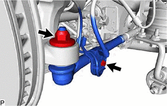
Remove the nut.
-
Remove the bolt and disconnect the skid control sensor wire.
-
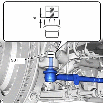
*a 1 mm (0.0394 in.) Install 2 spacers (SST spacer B) as shown in the illustration.
- SST
- 09960-20010 ( 09961-02060 )
Note
-
Be sure to install SST to prevent the spacer of the rear axle carrier sub-assembly from coming off.
-
Make sure that the clearance between the rear axle assembly and spacers (SST spacer B) is 1 mm (0.0394 in.) or more to prevent damage to SST.
-
Using SST, separate the rear steering tie rod assembly LH from the rear axle carrier sub-assembly as shown in the illustration.
- SST
- 09960-20010 ( 09961-02010 )
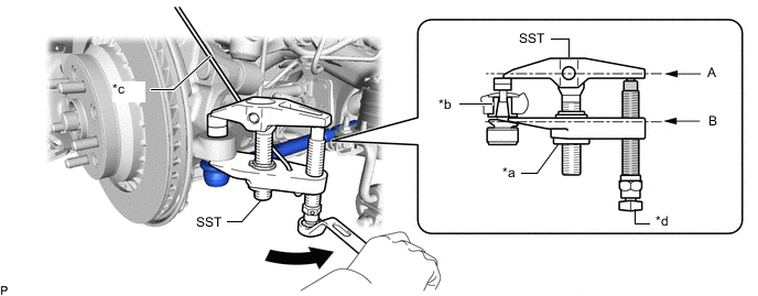
*a Nut *b Spacer *c Tie string without any slack *d Place wrench here 
Turn 
Molybdenum Grease CAUTION:
Apply molybdenum grease to the threads and the tip of SST bolt.
Note
-
Install SST so that (A) and (B) shown in the illustration are parallel. Otherwise, the ball joint dust cover may be damaged.
-
Be sure to place the wrench on the part shown in the illustration.
-
Be sure to tighten the string firmly to secure SST to the rear upper control arm assembly to prevent SST from falling off.
-
Make sure that SST is securely positioned on the spacer.
-
Do not damage the rear steering tie rod assembly LH ball joint dust cover.
-
If the spacer has come off, replace the rear axle carrier sub-assembly and rear steering link assembly with a new one.
-
-
DISCONNECT REAR STEERING TIE ROD ASSEMBLY RH
Tech Tips
Perform the same procedure as for the LH side.
-
REMOVE EXHAUST TAILPIPE ASSEMBLY
-
REMOVE REAR STEERING LINK ASSEMBLY
-
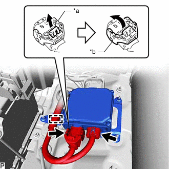
*a Lock of the Lock Lever *b Lock Lever Disconnect the 2 connectors from the rear steering control ECU.
Tech Tips
When disconnecting the connector with lock lever, pull out the lock of the lock lever and turn the lock lever as shown in the illustration.
-
Disengage the clamp.
-
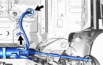
Remove the nut.
-
disconnect the grommet.
-
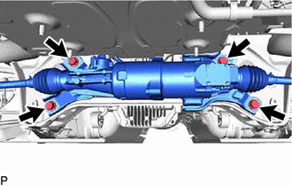
Remove the 4 bolts and rear steering link assembly.
Note
Do not drop the rear steering link assembly.
-